Start thermistor (ptc device) – Carrier 38SE User Manual
Page 10
Attention! The text in this document has been recognized automatically. To view the original document, you can use the "Original mode".
Carrier Standard Service Techniques Manual, Chapter 2, for
details. Use a 130 mfd start capacitor. Connect wires with
insulated probes to each capacitor terminal. Touch probes
to each side of run capacitor or to compressor motor
terminals R and S. Start compressor;
pull probes away after
3 seconds. Discharge start capacitor.
Run compressor for 10
minutes, then shut off and allow system pressure to
equalize. Try restarting without boost capacitor. If after 2
attempts (without boost capacitor) the compressor does
not start, add an accessory start capacitor relay package.
Unit Single-Phase Compressors
that are equipped with a
compressor
start thermistor (PTC device).
If compressor
will not start, check the thermistor with an ohmmeter as
follows;
1. Shut off all power to unit and wait 5 minutes for
thermistor to cool to outdoor temperature.
2.
Measure resistance of thermistor with ohmmeter.
Normal resistance readings are 50 to 90 ohms at 75 F
outdoor temperature.
3. If ohmmeter resistance reading is 0 or much higher than
90 ohms, the thermistor is defective and must be
replaced.
If start thermistor (PTC device) is good and compressor
will not start, disconnect the thermistor from starting circuit
and give compressor a temporary capacitance boost as
described above. Run compressor for 10 minutes, then shut
off and allow system pressure to equalize. Reconnect start
thermistor and try restarting compressor without boost ca
pacitor. If after 2 attempts the compressor does not start,
remove thermistor and add an accessory start capacitor re
lay package.
Compressor Removal
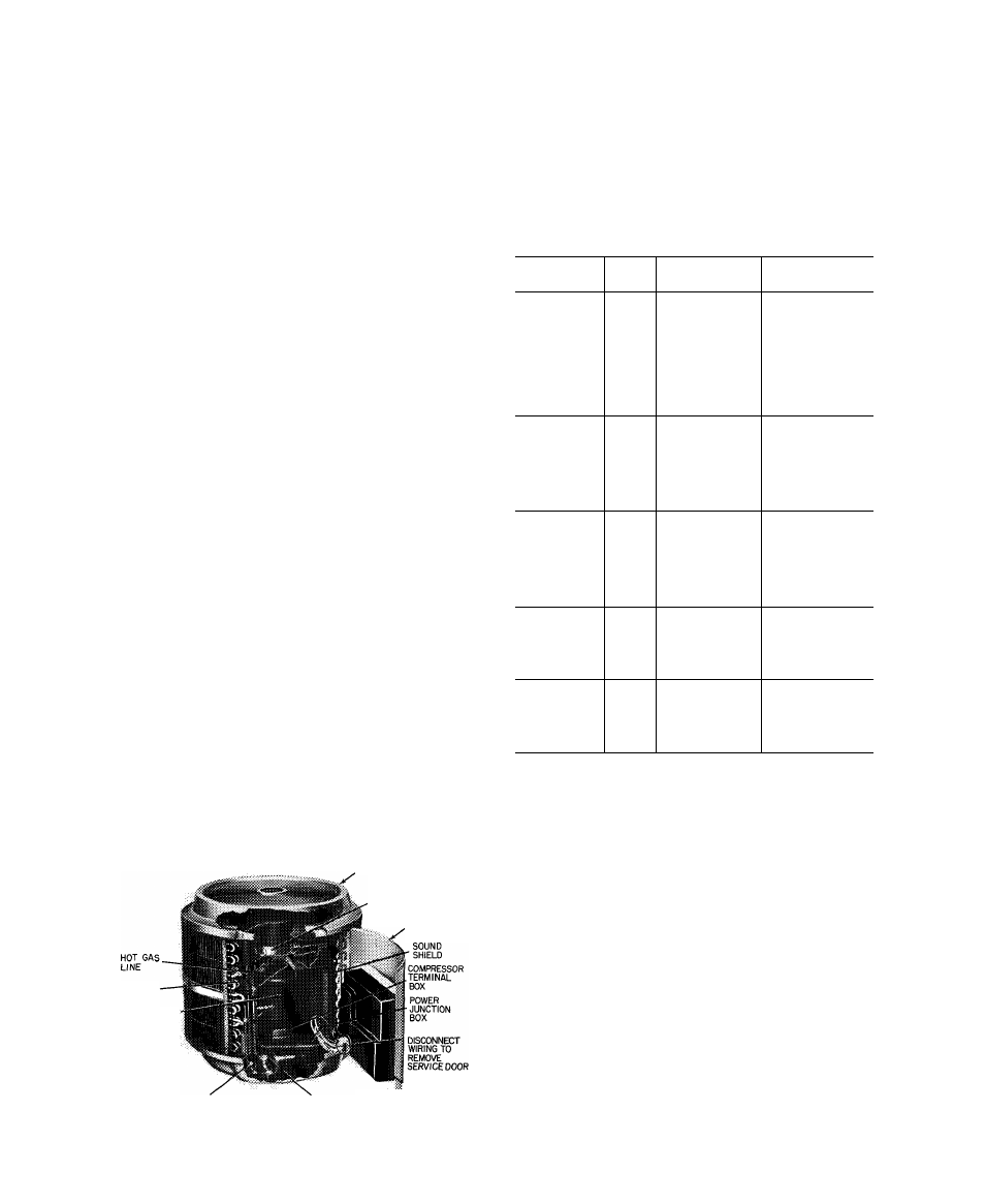
38GR; 38SE002,003,004 UNITS - See Table 9 for
compressor information and Fig. 8 for component location.
Shut off power to unit. Vent refrigerant to atmosphere or
use refrigerant removal methods shown in Carrier Standard
Service Techniques Manual, Chapter 1.
1. Remove unit top cover (grille). Open or remove service
door.
2. Disconnect fan motor leads from control panel located
on service door. See Fig. 7 and refer to Service Door on
page 3. Remove 6 screws holding fan motor orifice
assembly in place and lift assembly from unit.
3. Compressor outer sound shield is fastened to tube sheets
and to base pan. Loosen screws and remove sound shield
by sliding it straight up using tube sheets as guides.
4. (38SE only) — Warp top cover of inner compressor
sound shield upward to clear compressor process tube.
Carefully slide cover over the tubing.
.TOP GRILLE COVER
FAN MOTOR-ORIFICE
ASSEMBLY
SERVICE
DOOR
SUCTION
LINE
COMPRESSOR
5. (38SE only) — Slide inner compressor sound shield
terminal box cover upward and out.
6. Remove compressor terminal box cover, disconnect and
remove compressor power leads.
7. (38SE only) — Lift off inner compressor sound shield.
8. Unsweat suction and hot-gas lines.
9. Remove compressor hold-down bolts. Lift compressor
out thru top of unit.
Table 9 — Compressor Data
COND
V/PH
PRODUCTION
OIL RECHARGE
UNIT
COMPRESSOR*
(oz)
38GR002---
38GL400324
40.5
38GR002320
MD2723CB
43.2
38GR003---
38GR400234
31.5
38GR0033I0
MC3423CB
43.2
38GR004---
230/1*
38GC401564
45.0
38GR0043IO
MC4023CB
43.2
38GR045---
PC4Ó26AD
76 0
38GR005---
PC5326AD
76.0
38GR006---
PC6725AB
76 0
38GR003---
RF3522CJ
50.4
38GR0034Í0
MF3423CB
43 2
38GR004---
RF3922CJ
50 4
38GR0044Í0
200/3
MF4023CB
43.2
38GR045---
PF4626AD
76.0
38GR0£)5---
PF5326AD
76.0
38GR006---
PF6725AA
76 0
38GR003---
RG3522CJ
50.4
38GR0035I0
MG3423CB
43 2
38GR004---
RG3922CJ
50.4
38GR0045Í0
230/3
MG4023CB
43.2
38GR045---
PG4626AD
76.0
38GR005---
PG5326AD
76 0
38GR006---
PG6725AA
76 0
38GR004---
RH3922CJ
50 4
38GR0046Í0
MH4023CB
43 2
38GR045---
460/3
PH4626AD
76.0
38GR005---
PH5326AD
76.0
38GR006---
PH6725AA
76.0
38SE002---
MD2023CB
43 2
38SE003---
MD2723CB
43.2
38SE004---
230/1
MC3423CB
43.2
38SE045---
PC4Ó26AD
76 0
38SE055---
PC5326AD
76.0
LIQUID VALVE
SERVICE PORT
SUCTION VALVE
SERVICE PORT
JCONTROL
»PANEL
COVER
Fig. 8 — 38GR Condensing Unit with Service Door Open
shown italicized
000.
* Refer to Service Parts catalog for replacement compressor model
numbers.
The 38GR.SE single-phase compressors include start
assist.
38SE045,055 UNITS
1. Open and remove service door. See Fig. 7 and refer to
Service Door on page 3.
2. Disconnect fan motor leads and crankcase heater leads
from control panel located on service door.
3. Remove cover plate on compressor terminal box and
disconnect all leads.
4. Remove 4 screws holding compressor plastic sound
shield in place. Slide shield upward 6 to 10 inches.
5. Unsweat suction and hot-gas lines at compressor (dis
connect convenient connection at sight glass or filter-
drier).
6. Remove 3 screws holding coil to base pan.
7. From front of unit (coil-emblem side) hft complete
disconnected coil-fan-top cover assembly off from
compressor-base pan assembly.
10