Service door, Electrical data and wiring – Carrier 38SE User Manual
Page 3
Attention! The text in this document has been recognized automatically. To view the original document, you can use the "Original mode".
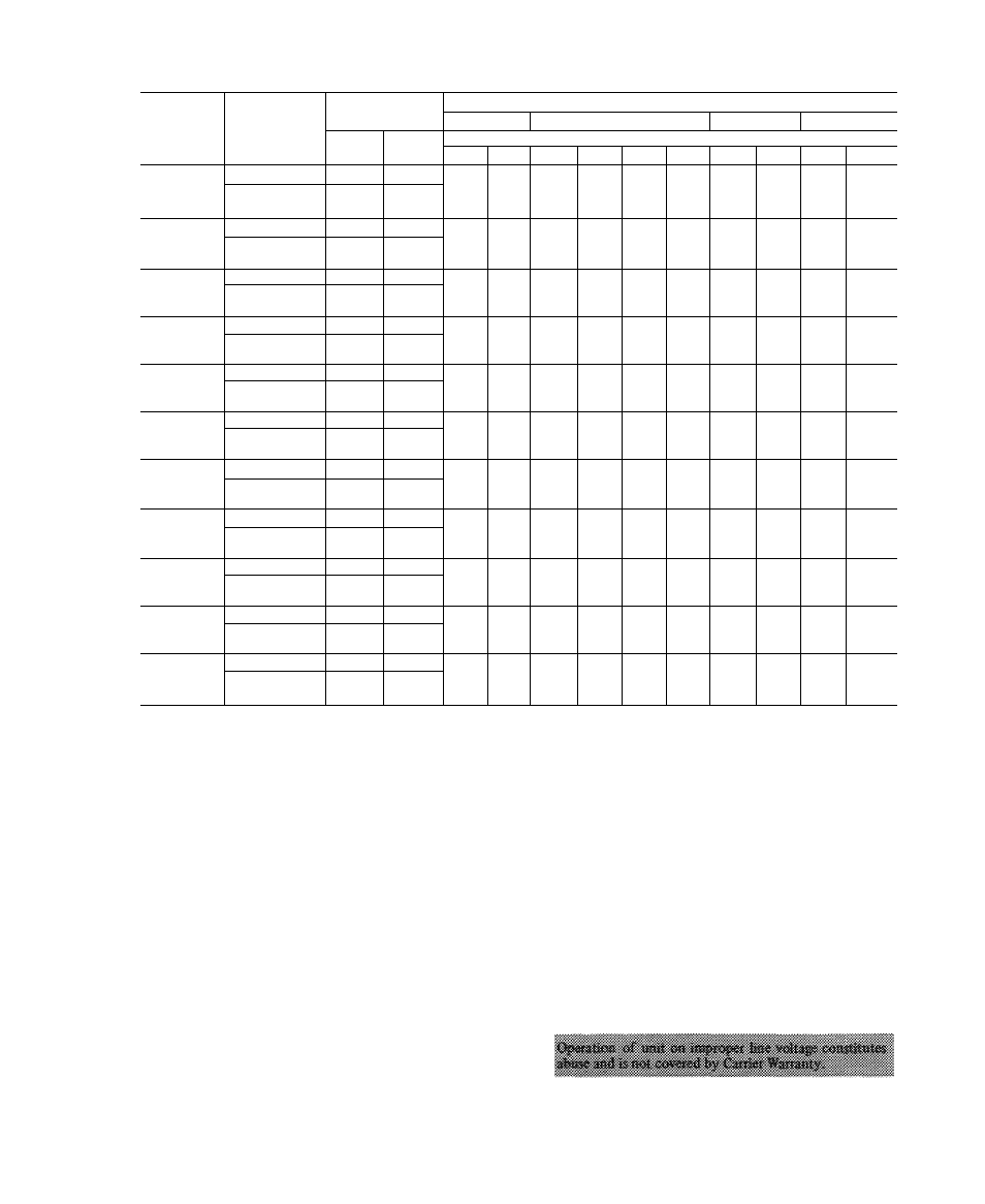
Table 3 — Field-Supplied Piping Data
COND
UNIT
REFRIG
CONTROL
MAX COND
UNIT HT (ft)
REFRIGERANT LINE LENGTH (ft)
25-50
51-75 76-100
101-125
126-150
Above
Evap
Below
Evap
Line Diameter (in. OD)
Suet
Liq
Suet
Liq
Suet
Liq
Suet
Liq
Suet
Liq
38GR002
TXV
90
90
%
V
4
Vs
V
4
Vs
V
4
Vs
V
4
Vs
Cap. Tube or
AccuRater'*'^
150
50
38GR003
TXV
90
90
%
%
V
4
Vs
V
4
Vs
V
4
Vs
V,
Vs
Cap. Tube or
AccuRater
150
50
38GR004
TXV
90
90
^4
%
V
4
Vs
Vs
Vs
Vs
V
2
Vs
Va
Cap. Tube or
AccuRater
150
50
38GR045
TXV
90
90
%
%
Vs
V
Vs
V.
Vs
V
Vs
Va
Cap. Tube or
AccuRater
ISO
50
38GR005
TXV
90
90
IVs
%
IVs
V
IVs
V
IVs
V
IVs
Vs
Cap. Tube or
AccuRater
150
50
38GR006
TXV
90
90
iVs
%
IVs
Vs
IVs
Vs
IVs
Vs
IVs
Vs
Cap. Tube or
AccuRater
150
50
38SE002
TXV
90
90
V
u
V
'8
V
/A
Vs
Vs
Vs
V
/8
Vs
Vs
Vs
Cap. Tube or
AccuRater
150
50
38SE003
TXV
90
90
Vs
V
'8
Vs
V'8
Vs
Vs
Vs
Vs
Vs
V'8
Cap. Tube or
AccuRater
150
50
38SE004
TXV
90
90
IVa
%
IVs
%
IVs
Vs
IVs
Vs
IVs
Vs
Cap. Tube or
AccuRater
150
50
38SE045
TXV
90
90
IVs
\
IVs
V
IVs
V
2
IVs
V
IVs
Va
Cap. Tube or
AccuRater
150
50
38SE055
TXV
90
90
iVa
%
IVs
V
IVs
V.
IVs
Va
IVs
Vs
Cap. Tube or
AccuRater
150
50
Cap. Tube — Capillary Tube
TXV — Thermal Expansion Valve
NOTES:
1 Systems with over 50 ft separation between condensing unit and evaporator require refrigerant
charge adjustment to ensure the proper superheat at compressor See Refrigerant Charging, page
5 Oil charge adjustment may also be required
2
Reduce liquid line diameter by 1/8-in OD (minimum 1/4-in OD) when evaporator is 20 ft or
more below condensing unit
3. Insert tube into compatible fitting. Wrap top and
bottom of service valves in wet cloth to prevent damage
by heat. Solder with low-temperature (450 F) silver
alloy solder.
4. Replace Schrader core.
5. Evacuate or purge system with field-supplied refrigerant.
SERVICE DOOR
Service door can be opened or removed for wiring or
servicing unit
Remove 3 screws from left side of service door (Fig. 1)
to swing door open.
Door Removal
— Turn power off. Disconnect wiring from
control panel mounted on door. Refer to Fig. 7 and 8.
After wiring is disconnected, lift door from roll pin hinges.
ELECTRICAL DATA AND WIRING
Field wiring must comply with local and national fire,
safety and electrical codes. Voltage to unit must be within
± 10% of voltage indicated on nameplate. On 3-phase units,
phases must be balanced within 2%. Contact local power
company for correction of improper line voltage.
See Table 4 for recommended wire and fuse sizes. When
making electric connections, provide clearance at unit for
refrigerant piping connections.