Power. circuit, Ot, (g), Cuit light should go off – Carrier 17CB User Manual
Page 9: Press on-stop switch (light goes off)
Attention! The text in this document has been recognized automatically. To view the original document, you can use the "Original mode".
power.
circuit
■
□
□
POWER
ON
STOP
START
oT, (g) □
OIL
PUMP
□
SAFETY
CIRCUIT
□
□
3. Press ON-STOP button
(light on). If SAFETY
CIRCUIT light does not
^
go on, check resets on
^
condenser high-pressure
safety, cooler low refrig
erant safety, bearing high temperature circuit
breaker, chilled water low temperature switch
and driver overload in starter. Check 3-amp
fuse in control center.
Manually trip and reset the bearing high
temperature circuit breaker, driver overload,
low refrigerant safety and chilled water switch
to be sure they cut off the safety light.
4. Press ON-STOP button
(light goes out). Remove
jumpers across terminals
(6^ and [0], [6^ and
5. Start chilled water and
condenser water pumps.
Press ON-STOP button
(light goes on).
■
□
□
POWER
ON
STOP
START
o
T
p
(|1 □
OIL
PUMP
□
SAFETY
CIRCUIT
■ ■ □
POWER
ON
STOP
START
□
OIL
PUMP
□
SAFETY
CIRCUIT
(g)
□
SAFETY
CIRCUIT
Turn on O I L - P U M P
switch for several seconds.
Pump should raise oil
pressure 25 to 27 psi
above refrigerant pressure
at machine shutdown con
dition. SAFETY CIRCUIT light should go on.
If oil pump operates but SAFETY CIRCUIT
light is out, check water flow switches.
7. Turn off OIL PUMP
■
■
□
switch. SAFETY CIR-
POWER
ON
START
CUIT light should go off.
□
OIL
PUMP
□
SAFETY
CIRCUIT
8.
With OIL PUMP switch
on, manually trip and
reset water pump switches.
SAFETY CIRCUIT light
should go off as each
switch is tripped. (Continuous operation of oil
pump is unnecessary during these checks.)
□
START
□
SAFETY
CIRCUIT
9. With OIL PUMP and
ON-STOP
switches
on,
and water pumps oper
a t i n g , p r e s s machine
START button (gas or
steam supply turned ofO
10. T u r n off OIL PUMP
switch. Oil pump must
continue operating.
11. Open oil pump main dis-
connect.
Driver
circuit
control must de-energize.
Oil pump will remain on
for 3 minutes.
12. OIL PUMP light goes out.
(g
■
■
□
POWER
ON
STOP
START
o
T
p
(g)
■
OIL
PUMP
□
SAFETY
CIRCUIT
■
■
□
POWER
ON
STOP
START
o
T
p
(g) □
OIL
PUMP
□
SAFETY
CIRCUIT
13. Press ON-STOP switch
(light goes off).
■
□
□
POWER
ON
STOP
START
gl
□
OIL
PUMP
□
SAFETY
CIRCUIT
14. Remove all power. Restore gas or steam supply
to drive. Restore power.
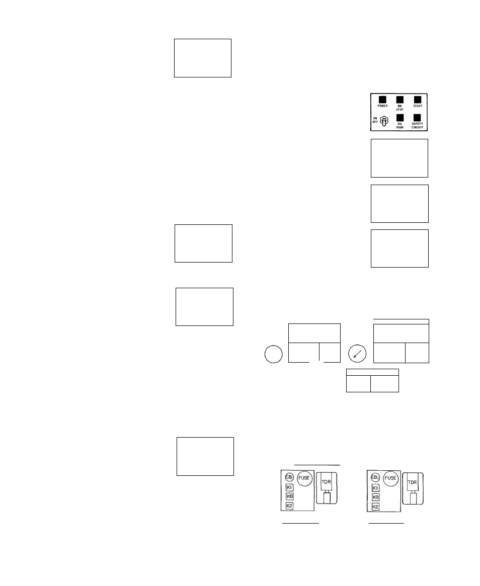
CONDENSER
/
□ □
□
POWER ON
START
STOP
□
OFF^
SAFETY
OIL PUMP CIRCUIT
COOLER
REFRIG
TEMP
CUT-OUT
TIT“
= K8
o
CONDENSER
PRESSURE
CUT-OUT
ELAPSED
TIME
INDICATOR
Z
CAPACITY
CONTROL
MODULE
RELAY MODULE
I I I I I I i~Tn
\
CONDENSER
□ □
POWER ON
STOP
□
START
OFF
OIL PUMP
□
SAFETY
CIRCUIT
REFRIG
TEMP
CUT-OUT
ELAPSED
TIME
INDICATOR
RELAY MODULE
I I I I I I I T-|
ELECTRONIC CONTROL
PNEUMATIC CONTROL
Fig. 7 — Control Center Components
(Gas Engine or Turbine Drive)