Start-up, Table 4 — setting safety controls – Carrier 17CB User Manual
Page 10
Attention! The text in this document has been recognized automatically. To view the original document, you can use the "Original mode".
START-UP
Preliminary Checks
1. Power on to circuit breakers, water pumps,
cooling tower fans
2. Cooling tower water level
3. Refrigerant level
4. Oil reservoir level
5. Oil reservoir temperature 140 F or warmer
6. Oil cooler plug cock (item 16, Fig. 2) partially
open, and any other valves in oil cooler line
fully open
7. Valves in chilled water and condenser water
circuits open and water circulating properly. Do
not permit water over 100 F to flow thru
cooler.
8. Air supply to pneumatic controls
9.
Purge valves and switches in “Normal-
Automatic” position. (Refer to chart attached
to purge cover.)
Compressor Rotation and Operation
Electronic Control: Set capacity control switch to
“Hold.”
Pneumatic Control; Turn off supply air to chilled
water thermostat and vane positioner.
Turn on OIL PUMP switch if gas engine or
turbine drive. Press machine ON-STOP and START
buttons (lights go on). As soon as the compressor
shaft begins to turn, note direction of rotation. If
not
counterclockwise as viewed from drive end,
stop compressor by pressing ON-STOP button
(light goes out) and correct condition.
If rotation is counterclockwise, let compressor
come up to speed and press ON-STOP button (light
goes out). Listen for any unusual sounds as
compressor coasts to a stop.
The program timer on electric drive units will
allow compressor restart 15 minutes after stop.
Checking Safety Control Settings
While performing these checks, carefully moni
tor
chilled
water
temperature
to
prevent
freeze-up. Protection by safety controls cannot
be assumed until all settings have been con
firmed as follows.
Shut off gas or steam supply to engine or
turbine. Open main disconnect (all power off to
starter and controls).
Electronic Capacity Control: Set capacity control
switch on “Hold.”
Pneumatic Capacity Control: Ensure that pilot
positioner operates as described in Setting Oper
ating Controls — Pneumatic. If compressor has
electric motor drive, set percent load knob on
demand limit control at 100% and turn calibration
screw fully clockwise.
Install jumpers across low refrigerant and low
chilled water cutouts as follows:
Electric Motor Drive — ^ to (4^ ; (0) to
[TT|.
Gas Engine or Turbine Drive
to
611 to [621; [71
Close disconnects, start compressor and check oil
pressure and temperature. With compressor run
ning, operate the guide vanes with the capacity
control switch or the pneumatic thermostat. Do
not exceed full load condition.
1. Check controls 1 and 2 as indicated in Table 4.
2.
Stop machine; open disconnects; remove
jumpers; and check controls 3, 4 and 5 as
indicated.
Table 4 — Setting Safety Controls
SAFETY OR CONTROL DEVICE
SAFETY OR CONTROL DEVICE
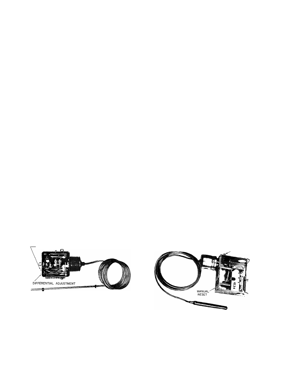
1. Chilled Water Low-Temperature Cutout and Recycle Switch
(Fig. 1).
-TEMPERATURE ADJUSTMENT
Set this switch to break at approximately 5 F below design
chilled water temperature, or at 36 F whichever is higher
Set the differential at 10 ± 1 F so that when the machine shuts
down automatically at approximately 5 F below the design
chilled water temperature it will restart at approximately 5 F
above the design water temperature
This control must break ahead of the refrigerant low-
temperature cutout switch or the machine will not recycle
automatically
2. Refrigerant Low-Temperature Cutout (Fig. 6 and 7)
CUTOUT
ADJUSTMENT
Set refrigerant low-temperature cutout at 33 F or one degree below
design refrigerant temperature, whichever is lower, while checking
temperature at thermowell near control center
10