Carrier 17CB User Manual
Page 14
Attention! The text in this document has been recognized automatically. To view the original document, you can use the "Original mode".
DEMAND LIMIT CONTROL
CALIBRATION
ADJUSTMENT
BANDWIDTH
DIAL
% LOAD DIAL
COVER
1. Set percent load dial at 100%.
2. Set Band Width dial at 3.
3.
Turn Calibration Adjustment screw fully
clockwise.
4. Run machine at 100% LLA by adjusting dial on
chilled water thermostat.
5. Turn Cahbration Adjustment screw counter
clockwise until guide vanes just begin to close.
6.
If hunting occurs, increase band width and
repeat steps 4 and 5.
7.
If control cannot be calibrated with above
procedure, check voltage signal from resistor in
starter. At 100% full load, voltage between
terminals 23 and 24 inside control center must
be 3.0 ± 0.1 volts. If not in this range, check
sizing of resistor in starter.
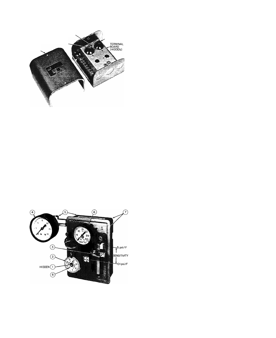
CHILLED WATER THERMOSTAT (PNEUMATIC)
ITEM
DESCRIPTION
1
SET POINT ADJUSTING SCREW
2
THERMOSTAT DIAL
3
SENSITIVITY SLIDER
4
SUPPLY AIR PRESSURE GAGE
5
SUPPLY AIR CONNECTIONS
6
CONTROL AIR PRESSURE GAGE
7
CONTROL AIR CONNECTIONS
8
DIAL RETAINING SCREW (2)
Preparation;
1. Ensure 25 psi supply air to thermostat.
2. Loosen Allen setscrew in sensitivity slider and
move slider halfway between midpoint and DA.
Re tighten screw.
Cahbration:
1. Turn thermostat dial until control air registers
15 psi.
2. Operate machine to reach design chilled water
temperature at design load. Maintain 15 psi
control air during pulldown by adjusting ther
mostat dial as required.
3. On reaching design chilled water temperature,
turn dial until control air pressure holds
machine at design conditions.
4. Hold setpoint adjusting screw stationary within
the dial post and set the thermostat dial at
design chilled water temperature.
^ Completion:
If vane hunting occurs, move sensitivity slider
away from DA. Sensitivity decreases as slider is
moved from 5 psi/F to the lower limit of 0.1 psi/F.
Trimming Refrigerant Charge
— After machine is
placed in operation, it may be necessary to adjust
the refrigerant charge to obtain optimum machine
performance.
When machine full load is available, slowly add
a sufficient amount of the remaining 200 lb of
refrigerant until the difference between leaving
chilled water temperature and cooler temperatures
reaches design conditions or becomes a minimum.
Shut down machine. Mark maximum refrigerant
level. Maintain refrigerant at this level.
Hot Alignment Check
— When all machine com
ponents have reached operating temperature (after
running near full load for approximately two
hours), a hot alignment check must be made.
1. Shut down machine.
2. Quickly disassemble couplings between com
pressor and drive (and gear, if used).
3. Check angular and parallel alignment in plan and
elevation. Indicators may be mounted as in Fig.
10. Refer to coupling manufacturer’s instruc
tions and to Carrier Standard Service Tech
niques, Chapter 15, for applicable procedures.
4.
After making adjustments, reassemble the
couplings and run the machine until it reaches
operating temperature.
5. Repeat steps 1 thru 3 until angular and parallel
alignment is within coupling manufacturer’s
specified tolerances.
14