Carrier 17CB User Manual
Page 15
Attention! The text in this document has been recognized automatically. To view the original document, you can use the "Original mode".
£
\
1
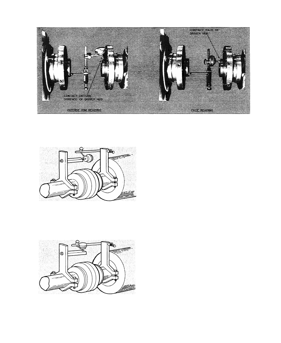
Fig. 10 — Checking Alignment with Dial Indicator
TO CHHCK ANGOi-AR AtJGNMSXT
TO CHECK PARALLSL AUGNMSiT
Fig. 11 — Alignment Check — Assembled Coupling
A second method of checking hot alignment
can be used if there is room on the shafts between
equipment and coupling to clamp a sturdy bracket.
Clamping tool, Part No. TS-170, is available for
this purpose thru Carrier Service Parts Department.
Check with your local Carrier Office. Dial indicator
must be obtained separately. Clamps must have
space to rotate with the shaft. This method is
quicker because couplings do not have to be
disassembled. Mount brackets and dial indicators as
in Fig. 11. Since both shafts are rotating together,
concentricity and condition of the faces are not
problems. The diameter used in the angular
alignment formula is the circle thru which dial
indicator rotates. This method is more accurate
since the diameter is larger.
Doweling
— After hot alignment is completed, the
compressor, gear and drive must be doweled to
their soleplates. This permits repositioning of
components if they have to be moved. Compressor
has four 3/4-in. holes for doweling.
1. Drill thru these holes into the soleplates Ream
holes with a tapered reamer with straight flutes.
2. Coat dowels with white lead or other lubricant
to prevent rusting.
3. Tap dowels lightly into position with a small
hammer. A ringing sound indicates the proper
seating.
Repeat these steps with gear and drive, keeping
dowels as vertical as possible. Dowel thru the four
3/4-in. holes on suction end of compressor base,
the two feet on high speed end of gear, and the
drive feet adjacent to gear. Refer to drive man
ufacturer’s instructions for additional details on
doweling this equipment.