Load recycle ■ □ n, N□ n, Press on-stop button (light goes on). ■ □ n – Carrier 17CB User Manual
Page 8
Attention! The text in this document has been recognized automatically. To view the original document, you can use the "Original mode".
5. Start chilled water and
condenser water pumps.
Press ON-STOP button
(Ught goes on).
6. Press OIL PUMP button
for several seconds. Pump
should raise pressure 25 to
27 psi above refrigerant
pressure
at
machine
shutdown
condition.
SAFETY CIRCUIT and
lights should go on.
7.
R e l e a s e O I L PUMP
button.
SAFETY
CIR
CUIT light and LOAD
RECYCLE light should go
out.
■
□
n
ON
STOP
START
OIL
PUMP
■
□ □
n
POWER SAFETY
LOAD
CIRCUIT RECYCLE
PROGRAM
TIMER
■
□
■
ON
STOP
START
OIL
PUMP
■ ■ ■
□
POWER SAFETY
LOAD
CIRCUIT RECYCLE
PROGRAM
TIMER
LOAD RECYCLE
■
□
n
ON
STOP
START
OIL
PUMP
■
□ □
n
POWER SAFETY
LOAD
CIRCUIT RECYCLE
PROGRAM
TIMER
8. With OIL PUMP button
depressed, alternately stop
and restart chilled water
and
condenser
water
pumps. SAFETY CIR
CUIT and LOAD RE
CYCLE lights should go out as each pump
stops. (Continuous operation of oil pump is
unnecessary during these checks.)
■
□
■
ON
STOP
START
OIL
PUMP
■ □ □
n
POWER SAFETY
LOAD
CIRCUIT RECYCLE
PROGRAM
TIMER
9. Shut off water pumps. Re
lease OIL PUMP button.
Press ON-STOP button
(light out). Replace tagged
wire on terminal fl 7j.
10
.
n
□
n
ON
STOP
START
OIL
PUMP
■
□ □
n
POWER SAFETY
LOAD
CIRCUIT RECYCLE
PROGRAM
TIMER
Press ON-STOP button
(light goes on).
■
□
n
ON
STOP
START
OIL
PUMP
■
■ ■
n
POWER SAFETY
LOAD
CIRCUIT RECYCLE
PROGRAM
TIMER
11. Press machine START
b u t t o n ( m o t o r leads
disconnected).
Oil pump starts within 30
seconds.
Compressor motor start
contacts
will
close
30
seconds later. Starter will
transfer to its run condi
tion 30 to 60 seconds
after starter is energized.
■
■
n
ON
STOP
START
OIL
PUMP
■ ■ ■
■
POWER SAFETY
LOAD
CIRCUIT RECYCLE
PROGRAM
TIMER
■
■
■
ON
START
OIL
STOP
PUMP
■ ■ ■
■
POWER SAFETY LOAD
PROGRAM
CIRCUIT RECYCLE
TIMER
■
■
■
ON
STOP
START
OIL
PUMP
■ ■ ■
n
POWER SAFETY
LOAD
CIRCUIT RECYCLE
PROGRAM
TIMER
12. Open oil pump main dis
connect. Starter must de
energize. OIL PUMP light
will remain on for approxi
mately 5 minutes.
OIL PUMP light goes out.
■
□
■
ON
STOP
START
OIL
PUMP
■ □ □
■
POWER SAFETY
LOAD
CIRCUIT RECYCLE
PROGRAM
TIMER
■
□
□
ON
STOP
START
OIL
PUMP
■ □ □
■
POWER SAFETY
LOAD
CIRCUIT RECYCLE
PROGRAM
TIMER
13. Close oil pump discon
nect. In approximately 10
minutes the program timer
will complete the anti
recycle portion of its cycle
and machine is ready to restart. (Total recycle
time is 15 minutes.)
■
□
n
ON
STOP
STAffT
OIL
PUMP
■
■ ■
n
POWER SAFETY
LOAD
CIRCUIT RECYCLE
PROGRAM
TIMER
14. Remove all power.
Restore power.
Reconnect motor leads.
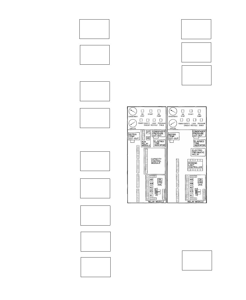
ELECTRONIC CONTROL
PNEUMATIC CONTROL
Fig. 6 — Control Center Components
(Electric Motor Drive)
Check Safety Control Operation (Gas Engine or
Turbine Drive)
Refer to machine control schematic in the
Operating and Maintenance Instructions for loca
tion of electrical terminals listed.
As checks are made, control panel lights
should appear as indicated in the diagrams.
1. Turn off main steam or
gas supply to prevent
drive from starting. Place
jumpers across oil switch
terminals (67} and
and flow switch terminals [69j and [70] inside
the control center.
□ □ □
POWER
ON
STOP
START
o
T
p
(g) □
OIL
PUMP
□
SAFETY
CIRCUIT