Carrier 17CB User Manual
Page 7
Attention! The text in this document has been recognized automatically. To view the original document, you can use the "Original mode".
4.
5.
6
.
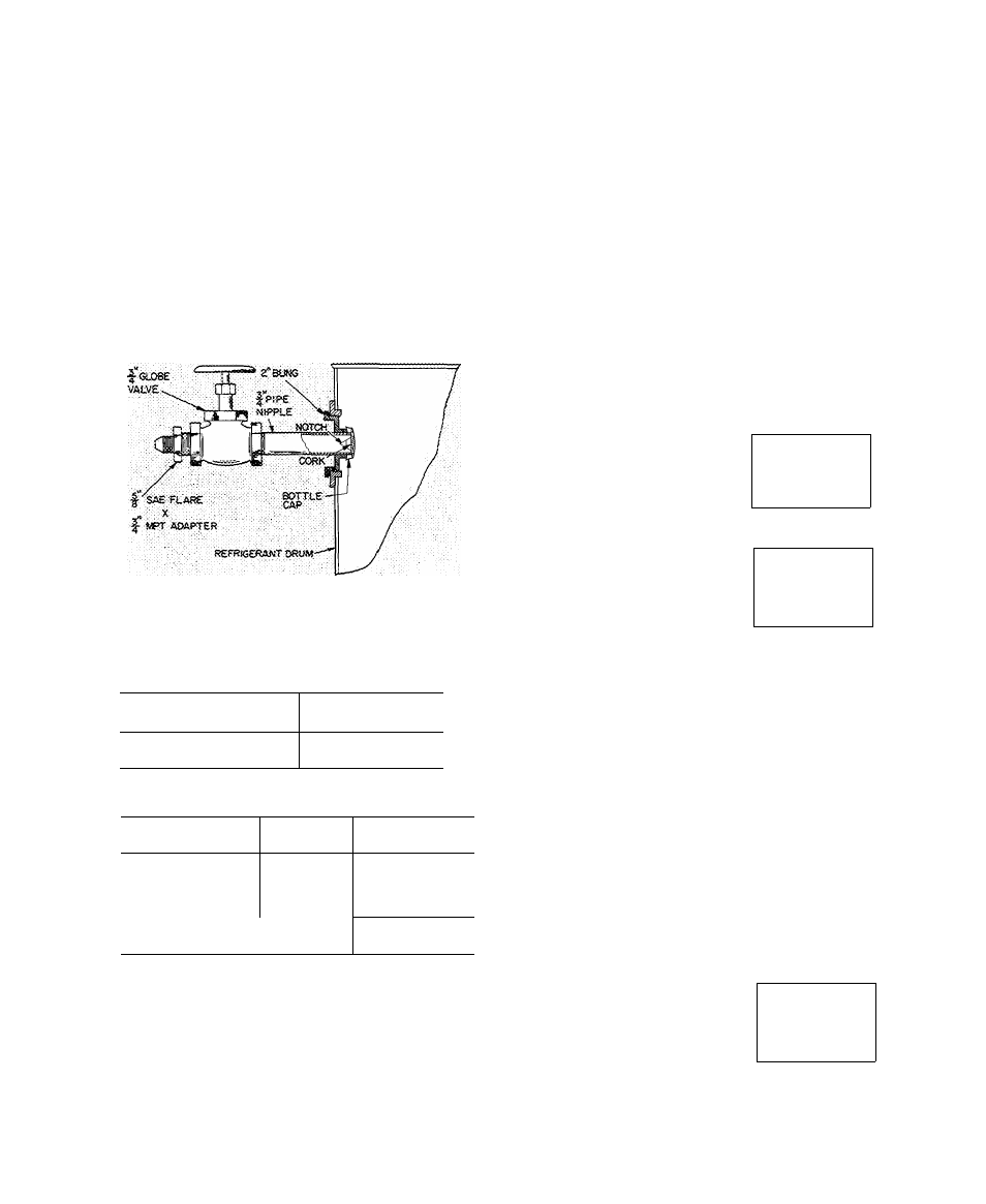
At a vacuiun greater than that indicated in
Table 2, refrigerant will flash into gas and
may cause tube freeze-up. Keep refrigerant
drums upright and admit refrigerant as a gas
until cooler vacuum is less than that listed in
Table 2.
The refrigerant supplied with the machine is in
excess of that required for initial charging.
Charge the amount shown in Table 3, less 200
pounds.
After the machine has been started, it may be
necessary to adjust the charge for optimum
machine performance. For this adjustment, see
Trimming Refrigerant Charge.
Fig. 5 — Drum Charging Valve
Table 2 — Pressures Corresponding to
32 F Saturation Temperature
REFRIGERANT
PRESSURE
(in. Hg vacuum)
n
18.05
114
3 85
Table 3 — Refrigerant Shipping Charges
MACHINE SIZE
REFRIG
SHIPPING
CHARGE (lb)
17CB1300
11
2800
17CB1400
1 1
3250
17CB1500
11
3250
17CB1600
11
3500
17CB1800
114
4400
17CB2000 j 114
4400
Drive
— It is good practice to operate the drive
separately before operating compressor. Refer to
drive manufacturer’s instructions for drive pro
tection devices and settings. Check turbine over
speed at this time. Reassemble couplings after
operating drive separately.
If drive is wired for automatic starting, it will
start when compressor START button is pushed.
Starting procedure of manually started drives may
be initiated after START button is pushed.
Purge
— Place the purge operating valves (Fig. 1) in
“Normal-Automatic” position as indicated in
operation 1 on the purge valve operation plate
(item 24, Fig. 1). Operate the purge momentarily
by placing the purge switch in “Manual” position;
then place purge switch in “Auto” position.
Air Supply — Pneumatic Control Only
— Check 25
psi air supply to pneumatic temperature controller
and pilot positioner.
Check Safety Control Operation (Electric Motor
Drive)
NOTE: Motor high temperature cutout is field
supplied only per customer’s request.
As the following checks are made, control panel
lights should appear as indicated in the diagrams.
□ - OFF
1. Open main disconnect (all
power off to starter and
controls). Disconnect main
motor leads in starter.
ON
n
□
n
ON
STOP
START
OIL
PUMP
n
□ □
n
POWER SAFETY
LOAD
CIRCUIT RECYCLE
PROGRAM
TIMER
2. Provide
power.
control circuit
n
□
n
ON
STOP
START
OIL
PUMP
■
□ □
n
POWER SAFETY
LOAD
CIRCUIT RECYCLE
PROGRAM
TIMER
■
□
n
ON
STOP
START
OIL
PUMP
■
■ ■
n
POWER SAFETY
LOAD
CIRCUIT RECYCLE
PROGRAM
TIMER
3. Press ON-STOP button
(light
goes
o n ) .
If
SAFETY CIRCUIT light
does not go on, check
resets on condenser high-
pressure safety, low refrig
erant safety, bearing and motor high tempera
ture circuit breakers and compressor overloads
in starter. Check 3-amp fuse in control center.
If SAFETY CIRCUIT Ught goes on but
LOAD RECYCLE light stays off, check the
chilled water recycle switch (auto-reset).
If both lights go on, manually trip and reset
motor and bearing high temperature circuit
breakers, compressor motor overloads and low
refrigerant temperature cutout to be sure they
cut off the safety Ught. Tripping the chilled
water recycle switch will cut off the LOAD
RECYCLE Ught only.
4. Press ON-STOP button
(Ught goes out). Remove
and tag gray striped wire
from control center ter
minal [l^. Refer to ma
chine control schematic in the Operating and
Maintenance
Instructions
for
terminal
location.
n
□
n
ON
STOP
START
OIL
PUMP
■
□ □
n
POWER SAFETY
LOAD
CIRCUIT RECYCLE
PROGRAM
TIMER