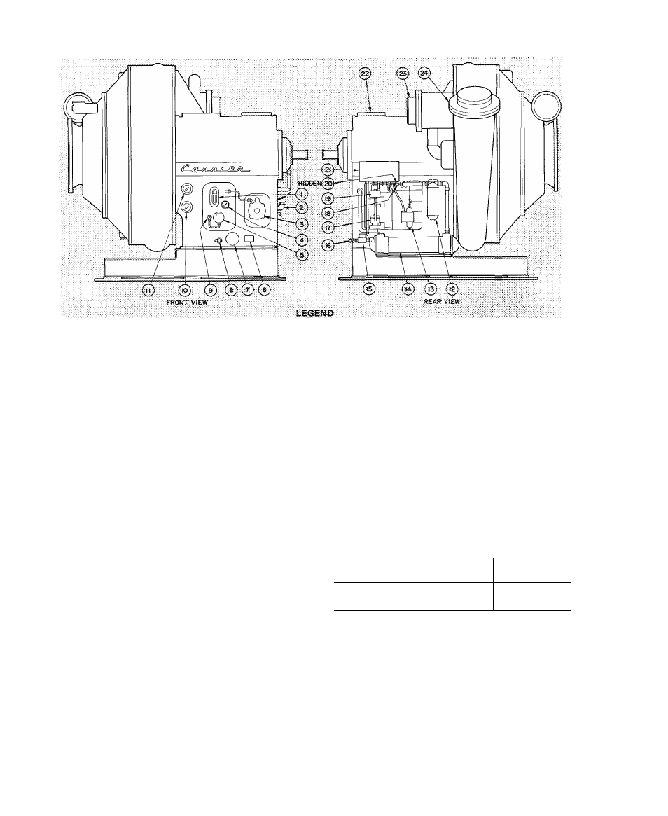
Fig. 2 — 17cb centrifugal compressor, Initial preparation – Carrier 17CB User Manual
Page 4
Attention! The text in this document has been recognized automatically. To view the original document, you can use the "Original mode".
I
1, OS fieservoif S5g,fit:G:!ass-
2- Oii^C^iargjng EJ
dow
,
Sc&i 01} Return
Sea! Cii Return Pomi>
Oil Reservoir Thermosneter
5, Oii Beater Terrninaf Sox
6. Ot! Pump !\tamep!ate
a
4.
7. 0:i Pomp Terminai Box
a Oii Ciwrging Vatve
■9. Oil Beater Thermostat
10. Oil Pressure Gege
tt. Main Searing Oi!
Thermometer
12
. Git Pilte;
15. Oii Pressure Oifferenirai
Switch
14. Oi! Cooler
: IS. Gii C>x>}er Solertoid Valve
16. Oil Cooler Plug Cock
T7. Porm "G" Solenoid Valve
15. Vai'te Speed Valve
IS. form "W' SoiShoid Valve
20. pii PressureReguiating Valve
21. Compressor Controi Wiring
dunctiott 8ox
22. i nspection Cover
23. Economizer Stubout
24. Oischarge Stt:i50ut
Fig. 2 — 17CB Centrifugal Compressor
INITIAL PREPARATION
C.AUTION: Do not start compressor or oil
purap, even for a rotation check, tmiess com
pressor is charged with oil and machine charged
with refri^rant.
Do not apply Yoitage of any kind while
machine is under dehydration vacuum.
Machine Tightness
— If machine leak testing and
dehydration was not completed at installation,
check machine tightness (including pumpout sys
tem) as described below. Dehydration must be
repeated if machine has been idle for several weeks
or more after initial dehydration.
Check for Large Leaks
— Using one of the methods
described below, pressurize the machine to the
level listed in Table 1. Do not exceed test pressure.
Listen for large leaks as the pressure builds up. If
test pressure holds for one hour, proceed with
Check for Small Leaks.
All 17CB machines may be pressurized with
cylinders of dry air or nitrogen thru the cooler
charging valve. Dry air or nitrogen charging is
preferable to purge or pumpout charging as it
ensures that moisture will not be introduced into the
machine. To pressurize with nitrogen (or dry air):
1. Connect a copper tube from charging valve to
pressure cylinder. Never apply full cylinder
pressure to the pressurizing hne. Follow steps 2
thru 5 in proper sequence.
2
.
3.
4.
Open cooler charging valve fully.
Open cylinder regulating valve slowly.
Observe cooler or condenser pressure gage and
close cylinder regulating valve when pressure
reaches test pressure listed in Table 1.
Do not exceed test pressure.!
5. Close cooler charging valve. Remove copper
tube.
Table 1 — Test Pressures
MACHINE SIZE
REFRIG
TEST
PRESSURE
17CB1300 thru 1600
R-11
8 to 10 psig
17CB1800 thru 2000
R-114
30 to 35 psig
Refrigerant 11 machines may be pressurized
with the purge pump. Ensure that electrical supply
to purge pump is 120 volts. Then follow operation
3 on the purge valve chart (item 24, Fig. 1).
Refrigerant 114 machines may be pressurized
with the pumpout unit. This method is detailed in
the section entitled Pumpout Procedures.
Check for Small Leaks
1. Pull a vacuum equal to 5 in. Hg (12.5 psia) by
using purge pump operation 2 (Refrigerant 11
machines), pumpout unit (Refrigerant 114
machines) or by applying a vacuum pump at
the cooler charging valve.