Carrier 17CB User Manual
Page 6
Attention! The text in this document has been recognized automatically. To view the original document, you can use the "Original mode".
I
Recheck Alignment
— Angular and parallel align
ment must be within coupling manufacturer’s
specified tolerances before machine is operated.
Refer to Carrier Standard Service Techniques
Manual, Chapter 15, for checking methods.
Leave couplings disassembled until drive is
tested and operated.
Check Grouting
— Make sure grouting was applied
during installation. Grouting should be completed
before machine is operated.
Inspect Piping
— Refer to piping diagrams provided
in Job Data and inspect piping to cooler, condenser
and oil cooler.
Chilled water should enter the lower nozzle of
the cooler and leave at the upper nozzle. Chilled
water temperature probe should be installed in
leaving chilled water line.
Condenser water should enter the upper con
denser nozzle and leave at the lower.
Ensure that pipes are vented and properly
suspended, with no stress on nozzles or water box
covers.
Measure water pressure drop across cooler and
condenser or across the pumps. Check to see that
water flow agrees with design flow.
Oil cooler water must be clean, with 85 F
maximum temperature and 200 psi maximum inlet
pressure. Refer to tag attached to cooler inlet
connection for pressure drop and velocity limits.
Check that any drive piping is installed per
manufacturer’s instructions.
Field Wiring
WARNING: Do not attempt to check high
voltage supply without proper equipment and
procedure. Serious personal injury can result.
Check with power company for specific
instructions.
Refer to Job Data wiring diagrams and check
field wiring as follows:
1. Wiring, voltage, supply, and rotation of all
electrical equipment; brine pump, condenser
water pump, tower fan.
2. Overload settings on all motor starters.
3. Wiring on all electrical devices on drive; auxil
iary oil pumps, pump starters, etc.
4. Wiring between drive and control center and
compressor junction box.
5. Wiring to pumpout compressor.
6.
Oil pump starter voltage against oil pump
nameplate voltage.
Lubrication
COMPRESSOR — Drain and flush out all shipping
oil;
then charge oil shipped with machine. It
conforms to Carrier oil specifications for centrif
ugal compressors (listed in the Operating and
Maintenance Instructions). Charge thru oil reser
voir charging valve (item 8, Fig. 2) to middle of
reservoir sight glass. Machine vacuum draws oil
from container.
Oil may also be added thru charging elbow
(item 2) in seal oil return chamber. The pump
(item 3) automatically transfers oil to the oil
reservoir.
IMPORT.ANT: After char^g oil, energize oil
heater (from its .separate l2D-voit source) to
minimize refrigerant absorption in the oiL Oil
heater indicating light comes on when heater is
energized. The thermostat should be set to
maintain a rhinimum temperature of 140 F at
shutdown. Adjust if required.
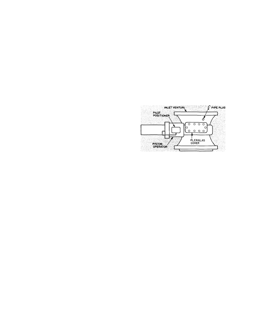
On pneumatic machines only,
add a small
amount of oil to the vane seal chamber thru 1 /4-in.
pipe plug (Fig. 4) until level reaches bottom of
rack and gear as seen thru Plexiglas cover.
Fig. 4 — Pneumatic Vane Shaft Seal Chamber
WARNING: Do not start oU pump^, even for a
rotation check, with madnne in dehydration
vacuum. Check rotation only after compressor
has been charged with oh and cooler has been
charged with refrigerant.
COUPLINGS — Lubricate couplings after they
have been reassembled. Follow manufacturer’s
recommendations for type of lubricant and
lubrication procedure.
NOTE. Do not reassemble couplings until drive has
been run separately.
SPEED INCREASING GEAR - Fill gear casing
with oil recommended by manufacturer. DO NOT
OVERFILL.
DRIVE — Refer to drive manufacturer’s instruc
tions for proper lubrication.
AUXILIARIES — Check all auxiliary pump motor
bearings for proper lubrication. Fill all oilers used
on shaft seals, bearings, etc.
Refrigerant Charge
1. Install a charging valve in the 3/4-in. drum
opening as shown in Fig. 5.
2. Connect a short length of plastic hose (R-11
only) or copper tubing from drum valve to
cooler charging valve.
3.
Circulate chilled water during the charging
process.