Carrier 17CB User Manual
Page 13
Attention! The text in this document has been recognized automatically. To view the original document, you can use the "Original mode".
max
\<%A
—
iol
\<%4-. ^
^Oi ir«&S5“
“»<*
\o\
\
-- MUtM. fft
i
mm
«Nft
^
9mi.y%
i V \ , WOlM«t
.
\
sosogn
i -------* m^Si
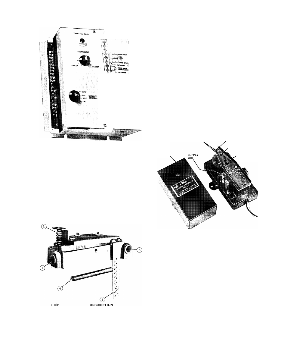
Fig. 9 — Capacity Control Module
(Gas Engine or Turbine Drive)
2.
Turn chilled water thermostat until design
chilled water temperature is maintained. Mark
thermostat at this position. If capacity control
vanes hunt, turn throttle range adjustment
counterclockwise in small increments until
hunting ceases. Chilled water thermostat may
require resetting.
Setting Operating Controls — Pneumatic
NOTE; if raachiiie has special pne^iipaiic con
trols, follow the instructions supplied in the job
data for their setting and adjustment.
PILOT POSITIONER
MAIN AIR CONNECTION (25 PSIG)
STARTING POINT ADJUSTMENT NUT
LEVER ARM
FOLLOWER SPRING
PILOT AIR CONNECTION
(FROM CONTROL CENTER)
Preparation:
1. Place jumper between terminals (L^ and
2. Open 25 lb air supply valve.
3. Remove cover from pilot positioner.
Calibration:
Rotate dial on chilled water thermostat to vary
pilot pressure. Observe pressure gage in pilot
supply line near pilot positioner and adjust starting
point nut (2) until piston operator (Fig. 4) begins
to move at 5 psi pilot pressure. Place follower
spring (4) in proper hole in level arm so that piston
operator opens 100% at 15 psi pilot pressure.
Completion:
1. Remove jumper from terminals [L^ and
2. Replace positioner cover.
ELECTRO-PNEUMATIC RELAY (Electric Motor
Drive Only)
SENSITIVITY SCREW
LOCKNUTS,
COVER
SET POINT SCREW
CONTROL AIR
(OUTPUT)
This control is factory calibrated to provide a
linear output signal of 3 psi at 6 volts d-c to 18 psi
at 15 volts d-c. Field recalibration should not be
necessary.
If calibration is required:
1. Establish 15 volt d-c input with 25 psi supply
air.
2. Turn sensitivity screw to obtain 18 psi or higher
output.
3. Adjust setpoint screw, if required, to set output
at 18 ± 1/4 psi.
4. Reduce input to 6 volts. Output should be 3 ±
1/4 psi. If low, turn sensitivity screw carefully
clockwise. If high, turn screw counterclockwise.
5. Re-check output at 15 volts. Repeat steps 3 and
4 if necessary.
1 3