Table 4 — setting safety controls (cont), R^fiyc – Carrier 17CB User Manual
Page 11
Attention! The text in this document has been recognized automatically. To view the original document, you can use the "Original mode".
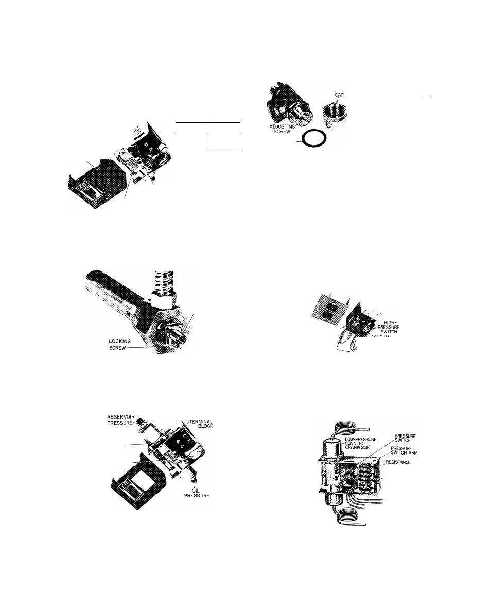
Table 4 — Setting Safety Controls (cont)
SAFETY OR CONTROL DEVICE
SAFETY OR CONTROL DEVICE
STOP MACHINE, REMOVE JUMPERS AND PERFORM RE
MAINING CHECKS.
3. Condenser High-Pressure Cutout (Fig. 6 and 7).
CUTOUT ADJUSTM^T
COVER
REFRIG
SETTING
11
15 psig
114
45 psig
RESET
BUTTON
CUTOUT SCALE
The condenser high-pressure cutout is factory set to shut the
machine down when condenser pressure reaches setting listed.
Isolate the switch and check setting with a metered supply of air.
4. Oil Heater Thermostat (Fig. 2).
SCREW
Set the oil heater thermostat to maintain a minimum oil reservoir
temperature of 140 F at shutdown
5. Low Oil Pressure Cutout (Fig. 2).
RANGE
DIAL ADJUSTMENTT
î
:
REMOVE METAL
COVER
DIFFERENTIAL
Low oil differential pressure switch is factory set to open at 11 ± 1
psi and close at 15 ± 1 psi differential pressure Operate oil pump
manually Remove cap and gasket from regulating valve and loosen
locknut. Turn adjusting screw counterclockwise to lower oil
pressure to 11 psi differential If safety does not trip, turn range dial
clockwise until cutout occurs
6. Oil Pressure Regulating Valve (Item 20, Fig. 2).
R^FiyC
11
114
SETTING*
15 psid
1 5-20 psid
*Settings given are above
reservoir pressure
SEALING
GASKET
Remove cap and washer and loosen locknut Turn adjusting screw
clockwise to raise oil pressure.
7. Vane Speed Valve (Electronic Machine Only)
Angle valve is located between oil line to main bearing and "F" and
“G" solenoid valves (items 17 and 19, Fig. 2) Set valve at full open
position
8. Chilled Water Flow Switch
Field supplied and installed. Follow switch manufacturer's instruc
tions for adjustment and maintenance
9. Main Bearing Oil Temperature (item 11, Fig. 2)
During machine operation, gauge should read 150 to 165 F. Adjust
water flow thru oil cooler with plug cock (item 16, Fig 2). Do not
exceed 7 gpm or pressure drop of 5 psig. Do not exceed 100 psi
working pressure
10. Dual Pressurestat for R-114 Pump-Down Compressor
COVER
CUTOUT AND
CUT-IN PRESSURE
. ADJUSTMENT
LOW-PRESSURE
SWITCH
COMPRESSOR.
CONNECTIONS
\jp PRESSURE
l-ADJUSTMENT ONLY
CUTOUT PRESSURE
ADJUSTMENT ONLY
High-pressure switch to open on rise at 45 psig Low-pressure switch
to open on fall at 2 0 in. Hg vacuum.
Set high-pressure switch by operating compressor and throttling
pump-down condenser water while watching pressure gauge.
Set low-pressure switch by operating compressor and gradually
shutting suction valve while watching pressure gauge.
11. Oil Safety Switch for R-114 Pump-Down Compressor
HIGH PRESSURE
CONN TO
OIL PUMP DISCHARGE
MANUAL
RESET BUTTON
CONNECT IN
SERIES WITH
CONTROL CIRCUIT
(SEE WIRING
DIAGRAM)
CONNECT TO
II50R 230V SOURCE
(SEE WIRING DIAGRAM)
Contacts open on drop in oil pressure. Cutout 11-14 psi; cut-in
16-19 psi differential between pump discharge and compressor
suction
Preset switch with an external air source
11