A warning, A caution – Carrier 58PAV User Manual
Page 15
Attention! The text in this document has been recognized automatically. To view the original document, you can use the "Original mode".
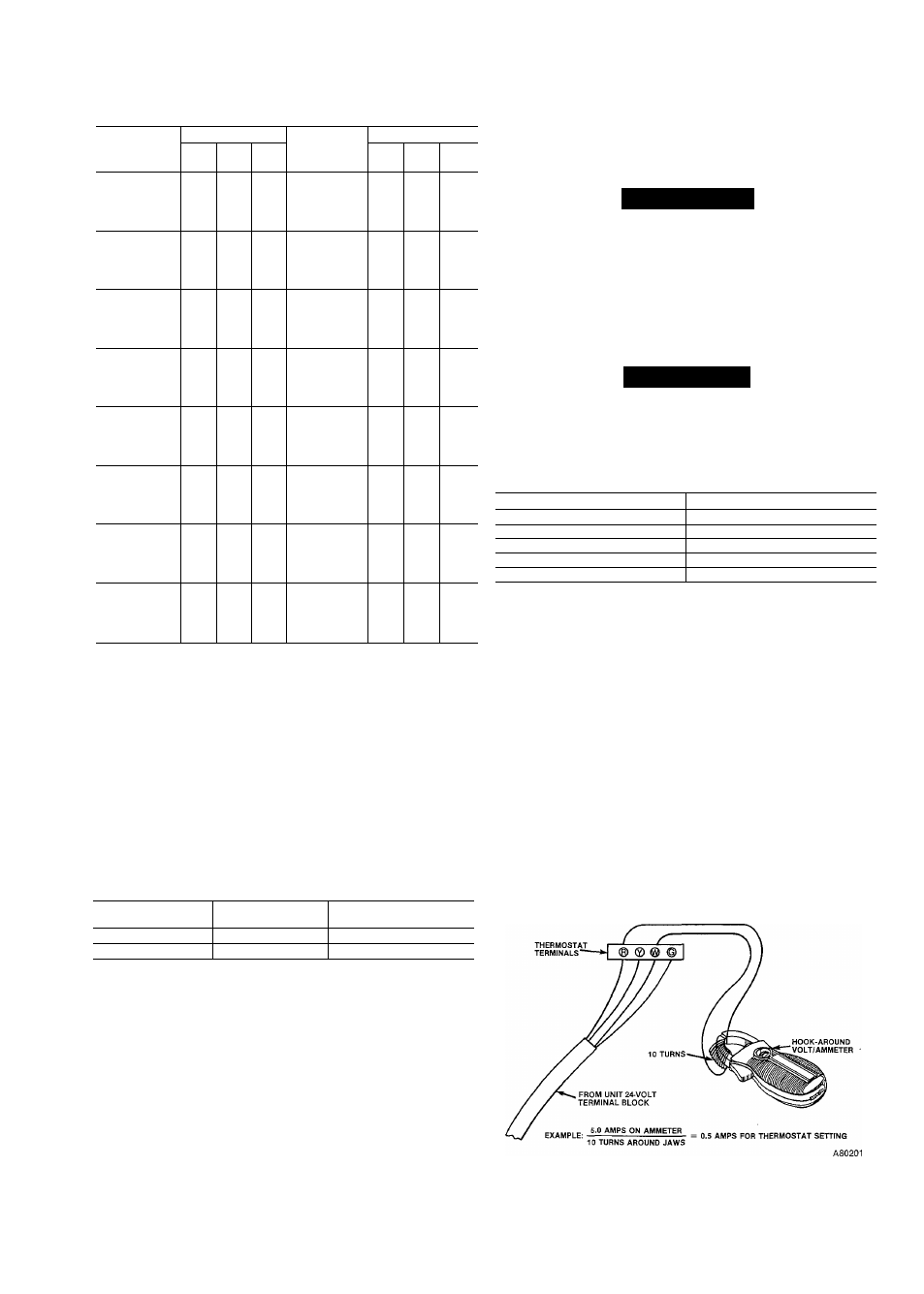
Table 16—Gas Rate Cu Ft/Hr
Seconds
SIZE OF TEST DIAL
Seconds
SIZE OF TEST DIAL
for one
1
2
5
for one
1
2
5
Revolution
cu ft CU ft CU ft
Revolution
cu ft cu ft cu ft
10
360
720
1800
50
72
144
360
11
327
655
1636
51
71
141
355
12
300
600
1500
52
69
138
346
13
277
555
1385
53
68
136
340
14
257
514
1286
54
67
133
333
15
240
480
1200
55
65
131
327
16
225
450
1125
56
64
129
321
17
212
424
1059
57
63
126
316
18
200
400
1000
58
62
124
310
19
189
379
947
59
61
122
305
20
180
360
900
60
60
120
300
21
171
343
857
62
58
116
290
22
164
327
818
64
56
112
281
23
157
313
783
66
54
109
273
24
150
300
750
68
53
106
265
25
144
288
720
70
51
103
257
26
138
277
692
72
50
100
250
27
133
267
667
74
48
97
243
28
129
257
643
76
47
95
237
29
124
248
621
78
46
92
231
30
120
240
600
80
45
90
225
31
116
232
581
82
44
88
220
32
113
225
563
84
43
86
214
33
109
218
545
86
42
84
209
34
106
212
529
88
41
82
205
35
103
206
514
90
40
80
200
36
100
200
500
92
39
78
196
37
97
195
486
94
38
76
192
38
95
189
474
96
38
75
188
39
92
185
462
98
37
74
184
40
90
180
450
100
36
72
180
41
88
176
439
102
35
71
178
42
86
172
429
104
35
69
173
43
84
167
419
106
34
68
170
44
82
164
409
108
33
67
167
45
80
160
400
110
33
65
164
46
78
157
391
112
32
64
161
47
76
153
383
116
31
62
155
48
75
150
375
120
30
60
150
49
73
147
367
d. Approved input ratings.
The U.S.A. ratings are approved for altitudes up to
2000 ft for natural and propane gases. Refer to
National Fuel Gas Code Appendix F, Table F-4 for
proper orifice sizing at high altitudes,
e. Canadian installations only.
The Canadian ratings are approved for altitudes up
to 2000 ft for natural and propane gases. High alti
tude ratings are from 2000 ft to 4500 ft above sea
level. See Table 17 for nominal burner orifice size.
High altitude rating includes a 10% derate as
required by Canadian standards.
Table 17—Canadian Orifice Size
Sea Level
High Altitude
Gas
0—2000 ft
20Ô0—4500 ft
Natural
43
44
Propane
54
55
2. Set temperature rise.
Do not exceed the temperature rise range specified on
the unit rating plate. Determine the air temperature
rise as follows:
a. Place duct thermometers in return and supply ducts
as near furnace as possible. Be sure thermometers
do not “see” heat exchangers so that radiant heat
will not affect thermometer readings. This is partic
ularly important with straight-run ducts.
b.
When thermometer readings stabilize, subtract
return-air temperature from supply-air temperature
to determine temperature rise.
c. Adjust air temperature rise by adjusting blower
speed. Increase blower speed to reduce temperature
rise. Decrease blower speed to increase temperature
rise.
A WARNING
Disconnect the electrical power before changing the
speed tap. A failure to follow this warning can cause
personal injury.
d. To change motor speed taps, remove the motor tap
lead (see Table 18) and relocate it on the desired ter
minal on the plug-in terminal block/speed selector
located on the blower housing.
A CAUTION
Recheck the temperature rise. It must be within the
Hmits specified on the unit rating plate. Recommended
operation at mid-point of rise or above.
Table 18—Speed Selector
Speed
Tap No.*
Common
C
Hi
1
Med-Hi
2
Med-Low
3
Low
4
*White wire from control box to common; black wire from control box to
cooling speed selection; red wire from control box to heating and con
stant fan speed selection.
3. Set thermostat heat anticipator.
The thermostat heat anticipation must be set to match
the amp draw of the electrical components in the R-W
circuit. Accurate amp draw readings can be obtained at
thermostat subbase terminals R & W. Fig. 16 illus
trates an easy method of obtaining the actual amp
draw. The amp reading should be taken after the
blower motor has started. See the thermostat manufac
turer’s instructions for adjusting the heat anticipator
and for varying the heating cycle length.
NOTE:
When using an electronic thermostat, set the cycle
rate for three cycles per hour.
E. Check Safety Controls
The flame sensor, gas valve, and pressure switch were all
checked in the Startup Section as part of normal operation.
Fig. 16—Amp Draw Check With Ammeter
15