A caution – Carrier 38QE User Manual
Page 9
Attention! The text in this document has been recognized automatically. To view the original document, you can use the "Original mode".
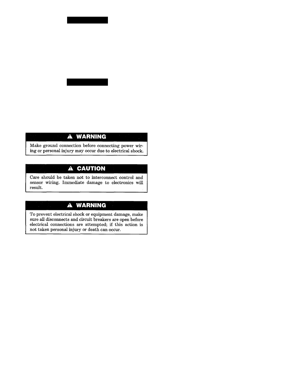
A CAUTION
Avoid running control and sensor wiring in parallel
bundles, conduit or pipe chases with the power wiring.
Power wiring can cause interference with the control
and sensor wiring. Maintain a minimum of 6 ins. of sep
aration between the control and sensor and power wir
ing. Control wiring should be secured to the refrigerant
piping between the compressor, indoor and outdoor
units.
A CAUTION
To prevent interference avoid running control and sen
sor wires in parallel with antenna emd telephone cables.
IMPORTANT:
The use of aluminum wire for any power or
control wiring is not allowed, all electrical wiring must be
copper; and all wiring specifications pertaining to the 38QE
system are specified as copper wire using American Wire
Gauge (AWG) sizing system
Step 11
—Install Control and Sensor Wiring
The control wiring consists of connections between the com
pressor section, water heater control box, indoor fan coil
and the thermostat. Sensor wiring is connected between the
outdoor fan coil and the compressor section. Sensor wiring
is also connected between the water heater tank and the
domestic water heating control box.
Control and sensor wiring requires standeird "thermostat
type and gauge of wire. The plenum cable listed in Table 2 is
recommended.
Compressor Section to Indoor Fan Coil Section
Run one length of 3 conductor wire. See Fig. 9 for connec
tion schematic. These three wires are used to control com
munications. To reduce the possibihty of electrical interfer
ence, route this cable along the refrigerant tubes and attach
with wire ties.
Compressor Section to Outdoor Fan Coil Section
Run one length of 3 conductor wire. See Fig. 9 for connec
tion schematic. These wires are used for outdoor unit tem
perature sensors. To reduce the possibility of electrical
interference, route this cable along the refrigerant tubes and
attach with ties.
Run one length of 4 conductor wire. See Fig. 9 for connec
tion schematic. Two wires will be used to power the water
heater contactor. The other two wires will be used for the
tank sensor connections. Do not interconnect the contactor
and sensor wires as immediate damage will result.
Domestic Water Tank Temperature Sensor to Water Heater
Control Box
See Fig. 9 for connection schematic. Use 2 conductor wire, if
extra length is required to make the connection.
NOTE:
For installations with a gas hot water heater and a
preheat tank, the water heater control box may be omitted.
Wire tank water temperature sensor directly to compressor
section as shown in Fig. 9.
Step 12—
Install Thermostat Wiring
The thermostat connections are described below for both
single and multiple zone installations.
The single zone instaRation requires a Parker relay pack
power supply accessory to provide power for the single zone
thermostat.
Single Zone—Fig. 10
Connect 3 wires from indoor fan coil section to monitor ther
mostat. Connect 5 wires from thermostat to power supply
module. Connect 2 wires from the power supply module to
the indoor fan coU section terminals R and C or an auxiliary
transformer that is capable of supplying 24 VAC. These
connections are shown schematically in Fig. 10. AH connec
tions within the indoor fan coU are described in the 40QE
Installation Instructions.
Multiple Zone (option)—Fig. 11
Connect 3 wires from indoor fan coil section to Monitor
Thermostat. AU additional zones are to be connected as
shown in Fig. 11 in parallel. All connections within the
indoor fan con and for each additional zone are described in
the 40QE Installation Instructions.
Other Accessories
Refer to the individual instructions packaged with optional
accessories for their control wiring. Also refer to the instal
lation instructions supplied with the 40QE indoor unit.
Step 1
3—Install Power Wiring
The 38QE system requires three branch circuits for power.
These include the compressor section, domestic water
heater and the indoor fan coil. The outdoor fan coil section
receives power from the indoor compressor section. The
electrical data for the 38QE system is shown in Table 4.
NOTE:
Be sure field wiring comphes with local emd national
fire, safety and electrical codes, and voltage to system is
within limits shown in Table 4 or on unit rating plate. Con
tact local power company for correction of improper volt
age. See Table 4 for recommended circuit protection device.
NOTE:
Operation of unit on improper line voltage consti
tutes abuse and could affect unit reliability. Do not install
unit in system where voltage may fluctuate above or below
permissible limits.
Install all branch circuits and disconnect switches in accord
ance with National Electric Codes (NEC) and appMcable
local codes. Locate disconnect(s) within sight from and read
ily accessible from the unit, per section 440-14 of the
National Electric Code (NEC).
208 Volt Operation
Model 38QE and 40QE units are factory wired for nominal
Domestic Water Heater Control Box to Compressor Section