Carrier 38QE User Manual
Page 13
Attention! The text in this document has been recognized automatically. To view the original document, you can use the "Original mode".
If the thermostat displays a hardware, software, heat pump,
or fan coil error code (HF,SF,HP or FC followed by a two
digit number), refer to the HydroTech 2000 Start-up and
Service Manual for further instruction on how to isolate and
clear system problems.
At initial start-up, thermostat(s) and bypass controller func
tions must be manually configured. This may be accom-
pHshed per the instructions located under the thermostat
cover with addressing exceptions as Hsted below:
NOTE: Be sure to correctly configure system for a variable
speed system and single- or multiple-zone application as
detailed in the instructions for rotary switch position F8, F9
and F13.
The proper configuration, programming and setup for
single- and multiple-zone installations are described here:
1. Address numbers 1 thru 2 are reserved for the 38QE
controls. No other devices can use address 1 thru 2. Be
sure the 38QE compressor section control module is set
to address 1 and the 40QE fan section control module
is set to address 2.
2. The monitor thermostat used for single-zone applica
tions should use address 3.
3. For multiple-zone apphcations the monitor thermostat
MUST BE addressed to the highest number followed
by the bypass controller (required) and then the slave
thermostats in any order (example: monitor thermostat
is address 6, bypass controller is address 5, zone 2
slave thermostat is address 4, zone 3 slave thermostat
is address 3.)
4. Power to indoor unit must be cycled after any change
to monitor thermostat address.
After all device features have been set or checked, return all
rotary switches to position 0 then, start-up and check the
operation of the 38QE variable speed system. Refer to
HydroTech 2000 Start-up and Service Manual.
To check the configm-ation:
1. Power up the thermostat.
2. Remove the thermostat cover.
3. Turn the rotary switch to the position indicated in
Table 5.
4. Check that the configuration settings are correct.
After the configuration values are correctly set:
1. Turn the rotary switch to position “0”.
2. Replace the thermostat cover.
These configuration items are the minimum required to get
the system running. There are many other options and fea
tures available through the remaining configuration set
tings. Refer to the Parker Reference Manuals for a complete
description and correct use of these additional features.
Step 17—Adjust Refrigerant Charge
38QE refrigerant charge adjustment or recharge must be
made by weighing-in the proper amount of refrigerant. Serv-
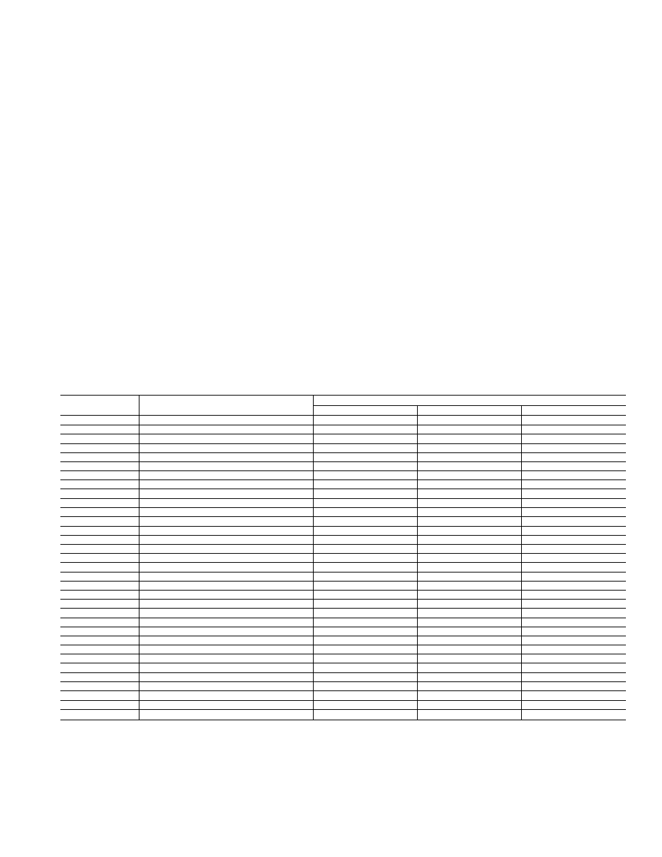
Table 5—Carrier/Parker HT2000 Home-Zone® Thermostat Configuration
ROTARY SWITCH
DISPLAY
POSITION
ROTARY SWITCH SETTING
FACTORY SET.
SINGLE ZONE
MULTIPLE-ZONE
0
COMFORT SETPOINTS
74 74
74 74
74 74
1
DEVICE ADDRESS
3
3
m*
2
SETBACK OVERRIDE TIME LIMIT
60
60
60
3
SETBACK SETPOINTS
85 65
85 65
85 65
4
DAMPER MAXIMUM OPEN POSITION
15
15
15
4
DAMPER VENTILATION POSITION
05
05
05
5
ZONE TEMP. SENSOR CALIBRATION
*
*
*
6
SUPPLY AIR TEMP. SENSOR CALIBRATION
*
*
*
7
COMMUNICATION CHECK
OFF
OFF
OFF
8
PRESSURE SENSOR ERROR CORRECTION
*
*
*
9
MAXIMUM PRESSURE SETPOINT
100*
100*
100*
A
HUMIDITY SETPOINT
50
50
50
B
SYSTEM MODE DEMAND/LARGE DEMAND
1
1 4
1 4
c
VARIABLE SPEED EQUIPMENT CONFIG.
*
«
*
D
NOT USED
BLANK
BLANK
BLANK
E
NOT USED
BLANK
BLANK
BLANK
F1
HTG./CLG. TIMEGUARD OVERRIDE
OFF
OFF
OFF
F2
CELSIUS TEMPERATURE DISPLAY
OFF
OFF
OFF
F3
ERROR CODE DISPLAY
ON
ON
ON
F4
2400 BAUD RATE
ON
ON
ON
F5
HEAT PUMP SYSTEM
ON
ON
ON
F6
LOCAL OUTSIDE AIR TEMP. SENSOR**
OFF
OFF
OFF
F7
DX COIL TEMPERATURE SENSOR
OFF
OFF
OFF
F8
MULTIPLE ZONE SYSTEM
OFF
OFF
ON
F9
VARIABLE SPEED EQUIPMENT
ON
ON
ON
F10
LOCAL HUMIDITY SENSOR
OFF
OFF
OFF
F11
EFFICIENCY OPERATING MODE
OFF*
OFF*
OFF*
F12
ALTERNATE INFORMATION DISPLAY
OFF
OFF
OFF
F13
HIGH/LOW TEMPERATURE LIMITS
OFF
OFF
OFF
F14
AUTO FAN OFF FOR HEAT
ON
ON
ON
F15
TEMPERATURE TREND STAGING
ON
OFF
OFF
F16
SETBACK LOCKOUT
OFF
OFF
OFF
FI 7
BYPASS CONTROLLER
OFF
OFF
ON
*VSE PARAMETERS ARE USED TO CONFIGURE OR TROUBLESHOOT THE VARIABLE SPEED SYSTEM. FOR DETAILS, REFER TO THE START-UP
AND SERVICE MANUAL FOR THE COMPRESSOR BEARING SYSTEM.
NOTE: ADDRESS THERMOSTAT FOR MULTIPLE-ZONE OPERATION AS FOLLOWS: SLAVE
2 ADDRESS
= m-3
MONITOR ADDRESS
= m
I
BYPASS CONTROL ADDRESS =
m-1
I
SLAVE 1 ADDRESS
= m-2
SLAVE x ADDRESS
= 3
X =
NO. OFZONES-1
4 ZONES MAX. (MONITOR -I- SLAVES)
(REFER TO COMPRESSOR UNIT INSTRUCTIONS
FOR OTHER ZONING LIMITATIONS)
13