The 38qe system software and safety devices, Table 2—accessory parts list – Carrier 38QE User Manual
Page 2
Attention! The text in this document has been recognized automatically. To view the original document, you can use the "Original mode".
domestic water heating control box emd domestic water
heating tank temperature sensor are supplied to control the
electric domestic water heating tank. The water heating is
accomphshed by pumping cold water from the cold water
inlet pipe at the top of the domestic water tank, through the
38QE refrigerant-to-water heat exchanger, and back into
the bottom of the tank.
The variable speed compressor operation allows the 38QE
system to control its output capacity to match the required
load through a wide range of outdoor temperatures and
operating modes.
Specially designed mating 40QE indoor units provide vari
able airflow control which is increased and decreased along
with the compressor speed. This feature, along with an elec
tronic expansion device, provide a level of comfort pre
viously unavailable for the home. It also enhances system
efficiency and provides much quieter operation them conven-
tioneil systems during most periods of operation.
The 38QE/40QE system has many other designed in com
fort and efficiency features including:
Carrier/Parker
Home-Zone®
thermostat
and
damper
options—to provide separate temperature control in up to
four areas.
Humidity control—add the optional humidistat to activate
special compressor and fan control which improves moisture
removal as needed. Humidistat plus humidifier also controls
moisture addition in the heat mode.
Air cleaning—connections provided for automatic control of
optional electronic air cleaner.
Utility demand limit interface—allows owner participation
in incentive programs offered by utilities for peak load con
trol, where available.
Unique defrost—the high temperature of the water in the
home’s hot water tank is used as the heat source for the
defrost cycle, rather than cooling the indoor air as with tra
ditional units. In addition, demand type defrost control pro
vides defrost when, and only when, it is required.
The 38QE/40QE system is available in capacity sizes shown
in Table 1. Accessories supplied with the system and other
available accessories are shown in Table 2.
APPLICATION LIMITATIONS
The 38QE system software and safety devices
Eire
designed
to prevent equipment operation under conditions that do
not comply with the application hmitations.
The 38QE product has certEun application hmitations which
are hsted below:
1
.
The 38QE compressor section and outdoor section are
to be matched to the specifically designed 40QE indoor
fan coil section. Permitted system configurations are
shown in Table 1.
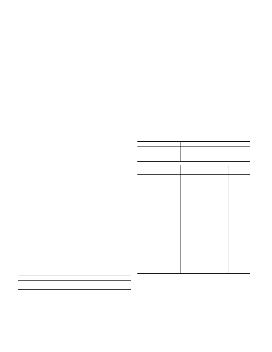
Table 1—Carrier Approved 38QE Systems
SYSTEM CAPACITY
2 TON
3TON
INDOOR COMPRESSOR SECTION
38QE024300
38QE036300
OUTDOOR FAN-COIL SECTION
38QE924300
38QE936300
INDOOR FAN-COIL SECTION
40QE024300
40QE036300
25 ft maximum vertical rise allowable
2
.
3.
The 38QE can only be used with Carrier/Parker Home-
Zone® thermostats. Monitor thermostat and slave ther
mostat model requirements are given in Table 2. All
thermostats must be properly configured and pro
grammed in order to obtain normal system operation.
The 38QE should not be used with systems containing
more than four (4) independently dampered zones. Use
6.
of the bypass controUer accessory is required for aU
zone apphcations.
4. The system wiU not operate in the cool mode at outdoor
temperatures below 45 F, and is not compatible with
tie Carrier Motormaster low-ambient control
; accessory. /
5, §The systern wiU not operate in the heat mode at out
door ternperatures above 75 F.
The compressor section must be located in a non-
freezing area because of water containing components.
Maximum air temperature surrounding the compressor
section must not exceed 105 F because of cooing
required for electronic controls.
The compressor section is designed to be installed on a
sohd mounting pad such as concrete. Do not install
compressor section in an attic, on a wall, or suspended
from a ceiling.
Refrigerant line lengths are hmited to 50 ft total maxi
mum, with 25 ft maximum vertical rise between indoor
and outdoor units.
9. For improved domestic water heating, locating the
compressor section within 15 ft of the domestic water
tank is desirable.
7.
8
.
Table 2—Accessory Parts List
ACCESSORIES SUPPLIED WITH COMPRESSOR SECTION
ORDERING NUMBER
DESCRIPTION
313204-701
Water Heater Control Box
313288-710
Water Temperature Sensor
Assembly
313243-201
Comp. Section Base Pad
ACCESSORIES REQUIRED OR RECOMMENDED
Zones
ORDERING NUMBER
DESCRIPTION
Singl
Mult
HT2000
Homezone Monitor Stat w/
clock
RQ
RQ
HZS (Version 2.7 or
higher)
Homezone Slave Stat
RQ
ZD-06,08,10,12,14,16
RD0810,0814,0818,0824
BCE
Round Dampers 6" thru 16"
RQ
Rectangular Damper 8x10
thru 24
Bypass Controller
RQ
RQ
TSR01
Relay Pack-Power Supply
RQ
PS02/PS01
Duct Pressure Sensor
RQ
PSPOO
Static Pressure Plok-up
RQ
RDS
Remote Duct Sensor
OP
OP
RRS
Remote Room Sensor
OP
OP
PCA-223
Plenum Cable—22 AWG, 3
)
conduc
RC
RC
PCA-225
Plenum Cable—22 AWG, 5
conduc
RC
RC
HL38MG026
Humidistat
RC
RC
—
Humidifier (49BF/FH/WS)
RC
RC
__
Electronic Air Cleaner (31
MPI
RC
RC
38TH900011
SX)
Outdoor Support Foot Kit, 4
in.
Outdoor Snow Rack, 18 in.
OP
OP
38YH900011
OP
OP
38YH900021
(024)
Outdoor Snow Rack, 18 in.
OP
OP
P504-8163S
(036)
Bi-flow Filter-Drier
RQ
RQ
HT01AX220
Transformer 40va
—
RQ
RQ—Required for installations.
RC—Recommended for installations.
OP—Optional for installations.
10. System is designed to work with conventional residen
tial sized electric water heating tanks only. NOTE: The
38QE should be installed with electric water heater
tanks that have two connections leading to the bottom
of the tank, as shown in Fig. 7a (cold water in, drain). If
only one connection to bottom of tank, install a preheat
tank, as for gas water heaters. Fig. 7b. For installation
with a gas water heater, a water preheat tank must be
installed.
i ;
<@)