A caution – Carrier 38QE User Manual
Page 7
Attention! The text in this document has been recognized automatically. To view the original document, you can use the "Original mode".
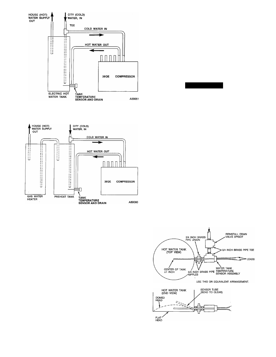
Fig. 7a—Installation with Conventional
Electric Water Heater
7. Insulate all water pipes with closed-cell foam type insu
lation with a nunimum wall thickness of 3/8 in.
8. If shut off valves have been installed in the water lines
between the tank and compressor section, slowly open
all valves. Bleed air from the heat pump water circuit
and circulating pump. First loosen the threaded union
on the pump outlet untU water flows out and no air is
present. Retighten union. Repeat process with xmion on
pmnp inlet. Then loosen air bleed screw in the center of
the circulating pump. The air bleed screw should only
be loosened, not totally removed, enough to allow air to
bleed. Retighten screw after system has been bled.
A CAUTION
Failure to bleed air from the water pump before energiz
ing will cause immediate pump failure. The pump
employs water-cooled and lubricated bearings; and if air
is left in the vicinity of the bearing, insufficient cooling
and lubrication will be available and bearing failure will
result.
ELECTRICAL CONNECTIONS
NOTE:
This equipment generates and uses radio frequency
energy. If not installed properly in strict accordance with
these installation instructions, it may cause interference
with televisions and/or radio reception. It has been tested
and foxmd to comply with the limits for a Class B comput
ing device in accordance with the specifications in Subpart
J of Part 15 of FCC rules (which are designed to provide pro
tection against such interference in a residential installa
tion). However, there is no guarantee that there will not be
interference in a particular installation. If this equipment
does cause interference to television and/or radio reception,
which can be determined by turning the equipment off and
on, the installer or serviceman should refer to “38QE Start
up, Troubleshooting and Service Guide.”
Fig. 7b—Installation with Gas Water Heater
and Preheat Tank
Tank Water Temperature Thermostat
Adjust the lower electric heater thermostat to the minimum
setting.
Water Piping Installation
1. Shut off all electrical power to domestic water heater.
2. Shut off water supply to domestic water heater and
drain tank.
Remove drain valve from bottom of tank which
requires sensor (Fig. 7a or 7b). Install pipe nipples and
tee and insteJl tank water temperature sensor as shown
in Fig. 8. Bend sensor up to avoid hitting water tanks
that have dome shaped bottoms.
Install second tee into tank sensor tee as shown in
Fig. 8. Install drain valve and connect water piping
between second pipe tee and hot water outlet connec
tion on the compressor section.
5. Install a tee fitting on the cold city water supply as
shown in Fig. 7. Install the water piping between the
tee fitting and the cold water inlet connection on the
compressor section.
6. Refill the hot water pipes and tank, purge air, and
check aff water connections for leaks.
HOT WATER FROM 38QE
COMPRESSOR SECTION
3.
4.
A90213
Fig. 8—Hot Water Inlet Connection
to Hot Water Tank