Fig. 3—outdoor accessory support feet, Orientation and location of equipment step 1, Step 2 – Carrier 38QE User Manual
Page 3: Step 3
Attention! The text in this document has been recognized automatically. To view the original document, you can use the "Original mode".
A90214
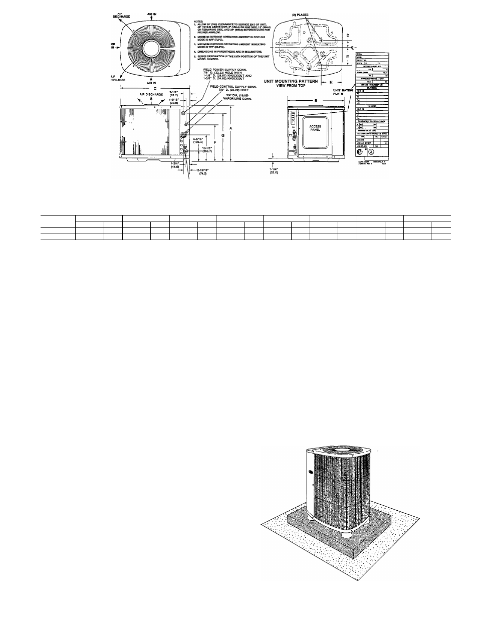
Fig. 2—Outdoor Section Dimensions
Dimensions
UNIT
A
B
C
D
E
F
G
H
SIZE*
(IN.)
(m m )
(IN.)
(m m )
(IN.)
(m m )
(IN.)
(m m )
(IN.)
(m m )
(IN.)
(m m )
(IN.)
(m m )
(IN.)
(m m )
38Q E924
31-7/8" •
809.6
30"
762.0
34-15/16"
887.4
4"
101.6
9-3/4"
247.6
21-1/2"
546.1
27-7/8"
708.0
8-3/16"
207.9
38Q E936
31-7/8"
809.6
38-5/8"
391.0
45"
1143.0
5-15/16"
150.8
11-13/16"
300.0
21-1/2"
546.1
27-7/8"
708.0
8-9/16"
217.4
ORIENTATION AND LOCATION OF EQUIPMENT
Step 1—
Inspect Equipment and Job Site.
A complete single zone system wül consist of the following:
1. Compressor Section
2. Outdoor Section
3. Indoor Section
4. Domestic Water Heater Control Box
5. Domestic Water Heater Tank Sensor
6. Homezone Monitor Thermostat
7. Homezone Power Supply Relay Pack
Unpackage and inspect imits for any damage. Füe claims
with shipper if necessary.
The compressor section package wül include an installation
packet, domestic water heater control box and tank temper
ature sensor.
The outdoor fan coü section will include an instaUation
packet. The indoor fan coü section wül include an instaUa
tion packet.
Consult local buüding codes and the National Electrical
Code (NEC) for special requirements.
When installing, aUow sufficient space for airflow clearance
(outdoor fan-coü section), wiring, refrigerant and water pip
ing and servicing unit. Position the outdoor section so water
or ice from roof cannot drop directly on top of unit. Position
the compressor section indoors and adjacent to the domes
tic water heating tank.
Step 2—
Install Outdoor Fan-Coü Section (38QE924 or
38QE936).
The instaUation data, dimensions, and connection for the
38QE924,936 outdoor section are shown in Fig. 2.
InstaU on a solid, level mounting pad—If conditions or local
codes require the unit be attached to pad, tiedown bolts
should be used and fastened thru knockouts provided in
unit base pan. Refer to unit mounting pattern in Fig. 2.
Position so snow or ice from roof or eaves cannot faU
directly on unit. Position to minimize direct sunlight on air
temperature sensor above service valves.
On rooftop applications, locate unit at least 6 ins. above roof
surface. Place xmit above a load-bearing waU and isolate
unit and tubing set from structure.
Arrange supporting members to adequately support unit
and minimize transmission of vibration to buüding. Consult
local codes governing rooftop applications.
For proper drainage the outdoor section must be raised off
the mounting surface. Fig. 3 shows unit with accessory sup
port feet installed. Use accessory snow rack in areas where
prolonged subfreezing temperatures or heavy snow occur.
Refer to separate instaUation instructions packaged with
the accessories.
Step 3—
Install Indoor Compressor Section (38QE024 or
38QE036).
The instaUation data, dimensions, and connection for the
38QE024, 036 compressor sections are shown in Fig. 4.
Locate unit in non-freezing area such as a basement, garage
or utility room. Indoor locations within the living space are
not recommended. Basement instaUations also require care
ful planning to avoid areas directly under or adjacent to
bedrooms, living rooms, etc. Locate unit near the domestic
water heater. AUow space for refrigerant and water piping.
A88277
Fig. 3—Outdoor Accessory Support Feet