Table 4—electrical data – Carrier 38QE User Manual
Page 11
Attention! The text in this document has been recognized automatically. To view the original document, you can use the "Original mode".
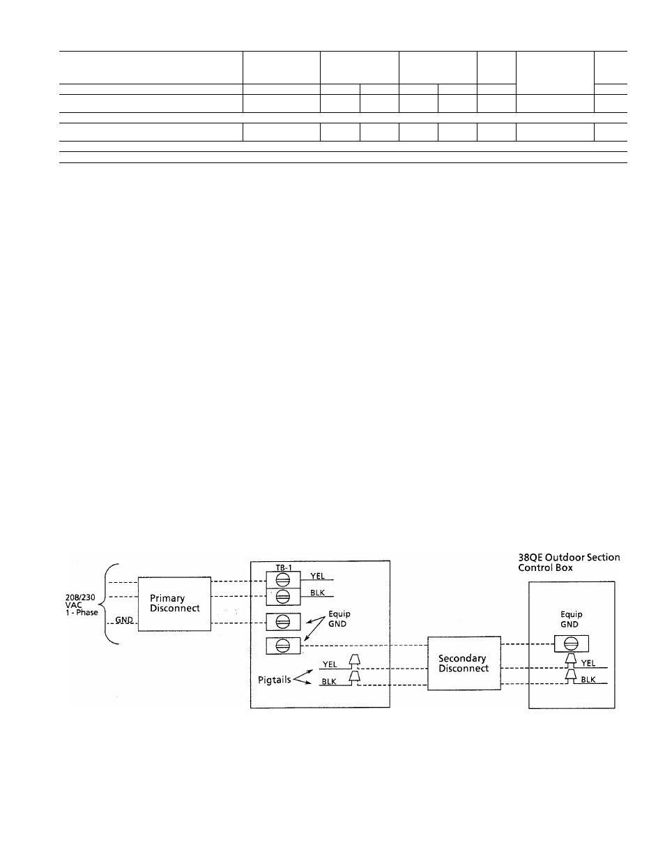
Table 4—Electrical Data
VOLT/PHASE
OPERATING
VOLT AG £♦
COMPRESSOR
FAN
MAX FUSE or
HACRTYPE
CIRCUIT BKR
AMPS
INDOOR COMPRESSOR SECTION
MIN
MAX
LRA
RLA
FLA
MCA
38QE024300
208/230/1
187
254
35.0
20.3
40
25.9
38QE036300
208/230/1
187
254
35.0
25.3
50
32.4
OUTDOOR FAN-COIL SECTION
38QE924300
208/230/1
187
254
.5
38QE936300
208/230/1
187
254
.7
WATER HEATER CONTROL BOX
38QE9XX300
208/230/1
187
254
20
20
FLA —Full Load Amps
HACR—Heating, Air Conditioning and Refrigeration
MCA —Minimum Circuit Amps
RLA —Rated Load Amps
LRA —Locked Rotor Amps
♦Permissible limits of the voltage range at which the unit will operate
satisfactorily.
♦♦Outdoor Coil Wiring—For 25-ft wire run or less, use minimum 14 AWG
wire size. For longer wire run, use same size wire as supply to compres
sor section.
230 V operation. The primary connection on control trans
formers must be rewired to the 208 volt wires for line volt
age between 187 emd 218 Volts. Refer to the 38QE Compres
sor Section label wiring diagram for location and wire identi
fication to rewire the two (2) transformers in the main con
trol box. Refer to the 40QE label wiring diagram for loca
tion and wire identification to rewire the transformer in the
accessory heater or cooling-only control package. Cap each
unused transformer wire with a wire nut and tape or, if the
unused lead has a push-on terminal, tape and protect any
exposed metal on the terminal.
Compressor Section
InstaR branch circuit disconnect of adequate size to handle
compressor section. Route line power leads from disconnect
through hole provided in compressor section top rear panel
and into the main control box. Connect ground wire to
ground lug. Connect main power to the terminal block
located within the main control box. The compressor section
wire label illustrates the terminal block location.
Rear panel wiring holes are shown in Fig. 4. See Fig. 12 for
connection schematic.
Outdoor Fan Coil Section
The outdoor fan coil section receives power from the com
pressor section. Provide a separate disconnect switch for
the outdoor fan cofi. section. Fig. 12 illustrates the connec
tions from the compressor section to the disconnect switch
and then to the outdoor fan coil section.
Connect ground wire to ground lug. Route power wires for
the outdoor fan coil section through the 7/8-in. hole provided
in the top rear panel of the compressor section. Splice wires
to pigtails with wire nuts.
Connect the power wires to the outdoor disconnect switch.
From the disconnect switch, extend wires through hole pro
vided in outdoor fan coil section and into line voltage sec
tion of control box. Splice leads to black and yeUow pigtails
with wire nuts. Connect ground wire to ground lug inside
control box.
Domestic Water Heater Control Box (Electric Heater Only)
Install branch circuit disconnect of adequate size to handle
domestic water heater. Fig. 13 illustrates the required wir
ing connection between the branch disconnect and the 38QE
38QE Compressor
Section Control Box
Splice Connection
Field Wiring
Factory Wiring
Fig. 12—Compressor Section and Outdoor
Section Power Connections
11