A caution – Carrier 38QE User Manual
Page 12
Attention! The text in this document has been recognized automatically. To view the original document, you can use the "Original mode".
38QE Water Heater
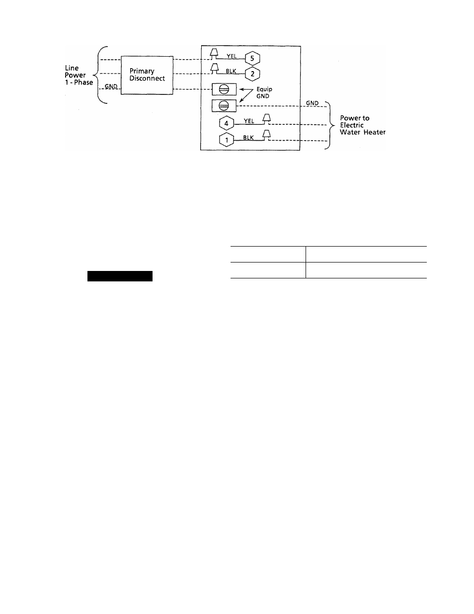
Control Box
Splice Connection
Field Wiring
Factory Wiring
A89056
Fig. 13—Water Heater Control Box Power Connections
(Electric Water Heater Only)
water heater control box and the domestic water heater
splice box.
A CAUTION
The water heater control box is designed for a maxi
mum of 20 Amps. Make certain that the water heater
does not exceed this 20 Amp limit. This system is not
designed to be installed with commercial grade electric
water heaters that may have greater than 20 Amp
requirements.
INDOOR
NOMINAL SPEED SETTINGS
UNIT
(MAX.-MIN.)
40QE024
5-2
40QE036
7-3
Indoor Fan Coil Section
Install branch circuit disconnect of adequate size to handle
indoor fan coil section. The proper wire sizing and lengths,
circuit breaker or fuse amp requirements are included in the
40QE installation instructions. Indoor power connection
diagrams are also included in the 40QE installation
instructions.
SYSTEM SET-UP ADJUSTMENTS
Step 14—
Inspect Indoor Blower Speed Limits
40QE fan coils are supplied with maximum and minimum
speeds preset at the factory. Maximum and minimum
blower speeds are determined by an 11-pin torque selection
connector located on the blower controller. (See indoor imit
installation instructions for component location.)
To Inspect Blower Speed Settings—
1. Remove indoor unit access doors.
2. Refer to indoor unit installation instructions to locate
11-pin speed selection connector on controller.
3. Check for proper factory speed pin settings on control
ler and adjust as shown below, if necessary.
Minimum and maximum settings may require adjustment
later. Refer to the 38QE and 40QE Start-Up and Service
Instructions.
Step 15—
Adjust Domestic Water Heating Tank Thermo
stats (Electric Heater Only)
Adjust the lower element thermostat setting to the mini-
Refer to 40QE Installation Instructions for proper Indoor Fan Coll Blower
setup.
mum value possible. This maximizes the heat pump water
heating capability. If this element is set above 100 F the
heat pump will not provide water heating. When the tem
perature setting of the lower element is above 100 F the
tank will operate as a conventional electric water heater.
(NOTE:
If the 38QE has been installed with a conventional
gas water heater the above steps are not required.)
Step
16—Configure Thermostats
In order for the 38QE system to work properly the thermo
stat must be corrrectly configured.
This procedure contains basic instructions for thermostat
operation. For detailed information on adjusting setpoints
or setup, refer to the instructions inside the thermostat
cover and the HydroTech 2000 Start-up and Service
Manual.
If the thermostat appears to malfunction during this proce
dure, refer to the appropriate Parker Thermostat Operation
Manual. HydroTech 2000 Start-up and Service Manual or
the Parker Homezone Troubleshooting Guide.
Make sure thermostat mode switches are set to OFF, and
FAN is set to AUTO.
Turn the indoor unit main disconnect switch ON (Note:
Transformers supplying power to multi-zone dampers and
thermostats may be on separate circuit from indoor unit.).
When the thermostat is powered up, the display will show
cooling and heating set points. If the display is blinking on
and off, it is indicating incorrect wiring connections or that
the thermostat is not receiving adequate power. Check wir
ing connections and supply voltage from the transformer.
The voltage must be 22 volts minimum. Make certain that
the thermostat ribbon cable has been inserted into the con
nector board correctly.
12