Jk caution, A caution, Caution – Carrier 38QE User Manual
Page 6
Attention! The text in this document has been recognized automatically. To view the original document, you can use the "Original mode".
A89059
(Top)
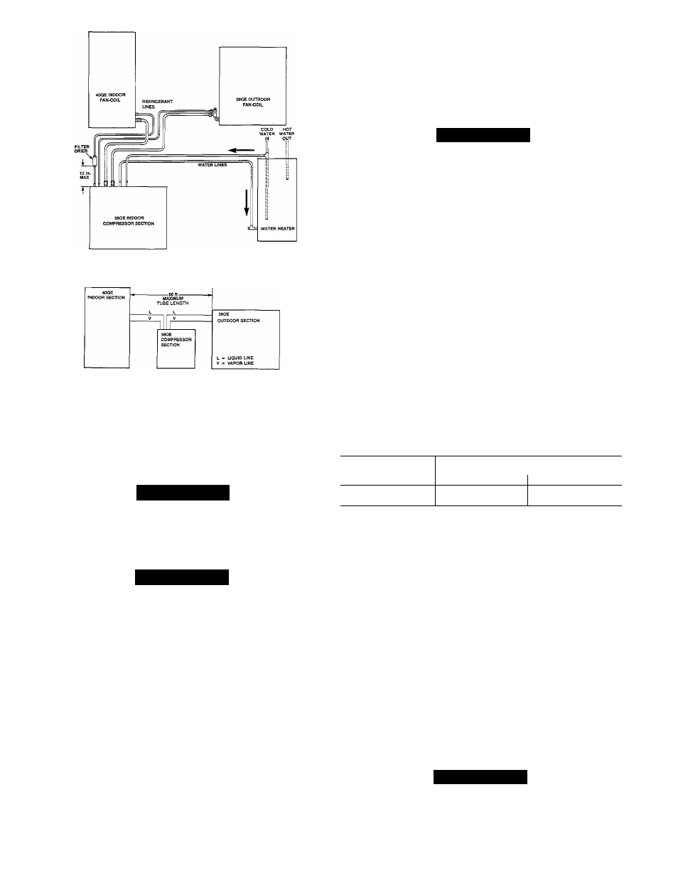
Fig. 5—38QE/40QE System Piping Schematic
A89059
(Bottom)
Fig. 6—Maximum Refrigerant Line Length
4. After wrapping the service valve with a wet cloth, the
tubing set can be brazed to the service valve using
either silver bearing or non-silver bearing brazing
material. Consult local code requirements.
Outdoor Fan Coil Section
Jk
CAUTION
A brazing shield MUST be used when tubing sets are
being brazed to the service valves to prevent damage to
the painted unit surface.
A
CAUTION
To avoid damage while brazing, service valves must be
wrapped with a heat-sinking material such as a wet
cloth.
Both the liquid emd vapor lines require sweat connections.
Use proper equipment and safety precautions when making
the sweat connection. The service valves on this unit are
both front and backseating. The service port does not con
tain a Schrader fitting. Do not attempt to connect manifold
until valve is fully backseated.
Service valves are closed from factory and ready for braz
ing. After wrapping the service valve with a wet cloth, the
tubing set can be brazed to the service valve using either sil
ver bearing or non-silver bearing brazing material. Consult
local code requirements.
Outdoor units contain correct system refrigerant charge for
operation with indoor unit of the same size when connected
by 25 ft of field-supplied or factory accessory tubing. Check
refrigerant charge for maximum efficiency (see Refrigerant
charging).
Indoor Fan Coil Section
The liquid and vapor tube fittings are flare and compatible,
respectively on the 40QE units. Use proper equipment and
safety precautions when making the flare connections.
Refer to the 40QE Installation Instructions.
Step 10—
Install Domestic Hot Water Piping
A CAUTION
Use only water piping, fittings and brazing material
that are suitable for Potable Water systems when con
necting the heat pump to the household water system.
Consult local codes.
The compressor section and domestic water heater should
be located as near as possible to each other. Total length of
interconnecting water piping between the compressor sec
tion and water heater should not exceed the lengths shown
in Table 3. The number of bends and pipe fittings should be
kept to a minimum. The use of shut-off valves in the water
lines between the domestic water tank and the compressor
section are not recommended as they may adversely affect
the system performance. (If valves are used, use only Ball or
Gate type). However compliance with local codes should be
followed. Failure to insulate pipes will result in performance
degradation..
Domestic Water Heating Tank
The 38QE can be installed with a conventional electric
water heater or with a gas water heater system. The basic
installation procedures are the same. However in the instal
lation with the gas water heater an insulated preheat tank
Table 3—Recommended Water
Piping Size
PIPE SIZE
ALLOWABLE TOTAL
ALLOWABLE TOTAL
PLUS
PIPING LENGTH (Ft)t
PIPING ELBOWS
1/2" nom (5/8" OD)
20
6^
3/4" nom (7/8" OD)
50
6**
♦Length can increase by 1.6 ft for each elbow less than 6.
♦♦Length can increase by 2.0 ft for each elbow less than 6.
tTotal length of cold and hot water pipes.
must be used. The preheat tank is essentially an electric
water tank without the electric heating elements.
Installation of the 38QE with a conventional electric water
heater is shown in Fig. 7a. Installation with a gas water
heater and preheat tank is shown in Fig. 7b.
Tank Water Temperature Sensor
The connection of the water heating lines to the tank
includes the installation of the tank water temperature sen
sor. The tank water temperature sensor is located within the
drain fitting of the tank. The fitting location is shown in
Fig. 7a,b. The detail for instaUing the sensor is shown in
Fig. 8.
Water connection tubes on the 38QE compressor section are
identified in Fig. 4. The two tubing stubs require field-
supplied sweat couplings or reducing couplings for connec
tion to water lines.
A CAUTION
A brazing shield must be used when tubing and fittings
are being brazed to the water stub tubes to prevent
damage to the painted unit surface.