Ob&îïêctéd betwëèù tbe ìkmti;|ìiiì – Carrier 58GS User Manual
Page 9
Attention! The text in this document has been recognized automatically. To view the original document, you can use the "Original mode".
#
m
OVERHEAT FUSE LINK — The furnace is
equipped with a fusible element to protect against
overtemperature conditions in the vestibule that can
result from inadequate combustion air supply.
WARNÌNG: 0o
rtot
bjpass tììc fusible element
4ÏÎÉ:
ob&îÏÊCtéd betwëèù tbe ÌKmti;|ÌIIÌ
lì
ii;i©pe}3Sÿi)Sîaife^:
the combiìi!tìou: air soppìy:..
etemeut vwth au idejRîicaîpari;
HYïOLFm.
m
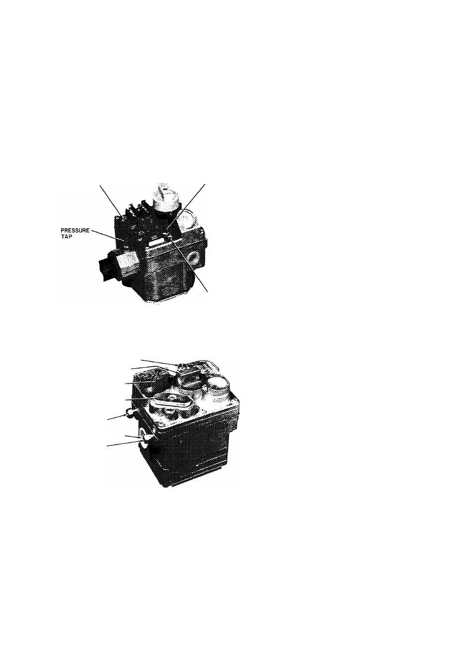
REGULATOR
ADJUSTMENT
PILOT
ADJUSTMENT
PILOT
TUBE
CONNECTION
Fig. 10 - BDP 646AW Gas Valve
PILOT ADJUSTING SCREW CAP
MANUAL SHUTOFF VALVE
AND PILOT COCK
LOW VOLTAGE
CONNECTIONS
REGULATOR ADJUSTING
COVER (ADJUST "Hi"
SIDE SCREW)
PILOT GAS LINE
CONNECTION
MAIN GAS CONNECTION
PRESSURE TAP
Fig. 11 — Essex 242 Gas Valve
COOLING — When the thermostat calls for cool
ing, power from the transformer energizes the
blower relay coil, closing its normally open contacts,
and energizing the blower motor on its cooling
speed. It continues to operate until the thermostat
is satisfied.
When the thermostat is satisfied, the circuit to
terminal (G) is broken, de-energizing the blower
relay coil which, in turn, opens its contacts, stopping
the blower motor.
AUTOMATIC GAS CONTROL VALVE The
automatic gas valve controls the flow of gas to both
pilot and main burners. All models have the manual
valve built into the automatic valve body. The
manual valve has only 2 positions: OFF and ON. It
does not have an intermediate position for pilot gas
flow only.
To shut off the gas manually, turn knob from ON
to OFF position. When in OFF position, the main
burners and the pilot flame are extinguished.
Starting Procedure
— Check to be sure that all
connections have been properly made, then pro
ceed as follows:
Use the procedure outlined on the Lighting In
struction Plate attached to the furnace. See Se
quence of Operation and perform the following
additional steps:
1. If supply line was not purged before connecting
furnace, it will be full of air. It is recommended
that pilot supply line be disconnected at pilot
shutoff valve or main gas valve, and supply line
be allowed to purge until odor of gas is detected.
Never purge gas lines into combustion chamber.
Immediately upon detection of gas odor, re
connect pilot supply tube. Allow 5 minutes to
elapse before lighting furnace.
2. Pilot flame should be soft blue in color.
For natural gas controls, flame should be of
sufficient length to provide good impingement
on element of pilot. Flame should extend upward
between carryover ports of 2 adjacent burners.
3. Pilot adjusting screw is located on main gas
valve, or pilot shutoff valve.
a. Remove capscrew; turn pilot gas full on and
adjust adjusting screw until desired appear
ance is obtained.
b. Replace capscrew.
Gas Input
— Determine the gas input as follows:
1. Natural Gas
a. Turn off all other gas appliances and pilots.
b. Measure time (in seconds) for gas meter test
dial to complete one revolution.
c. Divide 3600 by time noted and multiply result
by number of cu ft per revolution of test dial
(read off meter test dial).
________3600________ ^
seconds per revolution
cu ft per _ cu ft
revolution per hr