Notes for label wiring diagrams – Carrier 58GS User Manual
Page 3
Attention! The text in this document has been recognized automatically. To view the original document, you can use the "Original mode".
CAUTION: Use copper or copper-dad aluiai-
num conductors only. Use a separate branch
electrical circuit for this furnace.
A disconnect
ing means must be located within sight of, and
readily accessible to, the furnace.
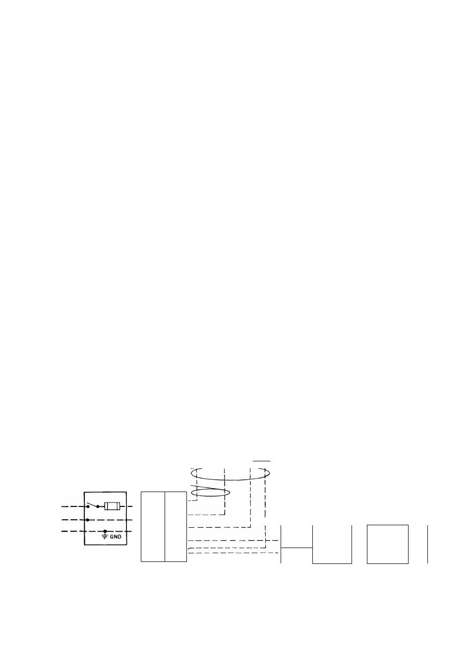
See Fig. 2 for wiring diagram showing the proper
field high- and low-voltage wiring. Make all elec
trical connections in accordance with the National
Electrical Code and any local codes or ordinances
that might apply.
WARNING: The unit cabinet m.ust have an
uninterrupted or unbroken electrical ground to
minimize personal injury if an electrical fanlt
should occur. This may consist of electrical
wire or approved conduit when installed in
accordance with e.Kisting electrical codes.
exposed to cold air infiltration, drafts from win
dows, doors, or other openings leading to the out
side, or exposure to air currents from warm or cold
air registers; or to exposure where the natural circu
lation of the air is cut off — such as behind doors,
above or below mantels, shelves, etc.
The thermostat should not be exposed to heat
from nearby fireplaces, radios, televisions, lamps,
or rays from the sun. Nor should the thermostat be
mounted on a wall containing pipes or warm air
ducts, or a flue or vent that could affect its
operation and prevent it from properly controlling
the room temperature. Any hole in the plaster or
panel thru which the wires pass from the
thermostat should be adequately sealed with suit
able material to prevent drafts from affecting the
thermostat.
LOW-VOLTAGE WIRING — Make field low-
voltage connections at the low-voltage terminal
strip. See Fig. 2.
Set the thermostat heat anticipator at the
settings indicated below. If additional controls are
connected in the thermostat circuit, their amp draw
must be added to this setting. Failure to make the
setting will result in improper operation of the
thermostat.
58GS050 thru 150 sizes with
BDP 646AW gas valve.
Heat/Cool or Heat only models................ 0.55 amp
58GS175 size with Essex 242NS gas valve,
Heat/Cool models.......................................0.65 amp
With addition of automatic vent damper, antici
pator setting should be 0.12 amp.
The room thermostat should be located where it
will be in the natural circulating path of room air.
Avoid locations where the thermostat would be
NOTES FOR LABEL WIRING DIAGRAMS
1
Screw terminals for field wiring connections
1/4-in quick connect terminals
3
L"
If
J Heating fan relay contact is normally closed until
r "
1 1 5
vac is applied to furnace
4
To change motor speed, move black or red wire to desired speed
setting
5
If any of the original wire as supplied with the appliance must
be replaced, it must be replaced with AWM (105 C) wire or its
equivalent
6 Motor is thermally overload protected
7
Factory speed selection is tor average conditions See installa
tion instructions for optimum speed selection Motor may be 3
or 4 speed
8 Symbols are an electrical representation only
FOUR WIRE-
©Cp
TWO WIRE HEATING ONLY
JL
Jl
©-■
■=r
&
&-
LOW-VOLTAGE
TERMINAL BLOCK
Field
Low-Voltage
Wiring
Field
High-Voltage
Wiring
Factory Low-Voltage Wiring
THERMOSTAT
TERMINALS
I TWO WIRE
CONDENSING
UNIT
.
q
^JZL
-CHMV
—
-Ijj^
— ———
= GN0
SINGLE
PHASE
NOTE: If any of the original wire as supplied, must be replaced,
use same type or equivalent wire
Fig. 2 — Heating and Cooljng Application Wiring Diagram