Filter – Carrier 58GS User Manual
Page 7
Attention! The text in this document has been recognized automatically. To view the original document, you can use the "Original mode".
PRINTED-CIRCUIT CONTROL CENTER —
Each furnace features a printed-circuit control
center to aid the installer and serviceman when
installing and servicing the unit. See Fig. 6. A
low-voltage terminal board is marked for easy con
nection of field wiring and accessories.
w
c
^
^
^ ^
Fig. 6 — Printed Circuit Control Center
CONTROL BOX
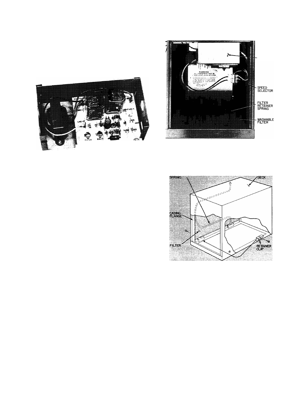
Fig. 7 — Filter Installed for Bottom Inlet
Filter
CAUTION: Air deHvety above cfm re
quires that both sides of faraace be used.,
or a combination of one side and bottom,
or bottom only.
FILTER ARRANGEMENT — The filter is factory
installed in the bottom of the furnace. This is for
bottom inlet application. See Fig. 7.
NOTE: Remove and discard bottom closure panel
when bottom inlet is used.
For side inlet application, see Fig. 1 for the
opening size. Remove the filter from the bottom of
furnace and relocate at the side by performing the
following steps:
1. Remove screws from filter retainer clips at both
sides of furnaee.
2. Remove retainer spring and position both clips at
inlet side of furnace.
3. Remove filter from bottom and position on inlet
side of furnace.
4. Place retainer spring over filter, making certain
to position front of retainer spring behind flange
of the casing side.
5. Install the retainer spring in the holes provided —
one in the bracket at bottom rear and the other
in the hole in blower deck. See Fig. 8.
Fig. 8 — Filter Installed for Side Inlet