Table 6 — air quantity limits – Carrier 50DP User Manual
Page 9
Attention! The text in this document has been recognized automatically. To view the original document, you can use the "Original mode".
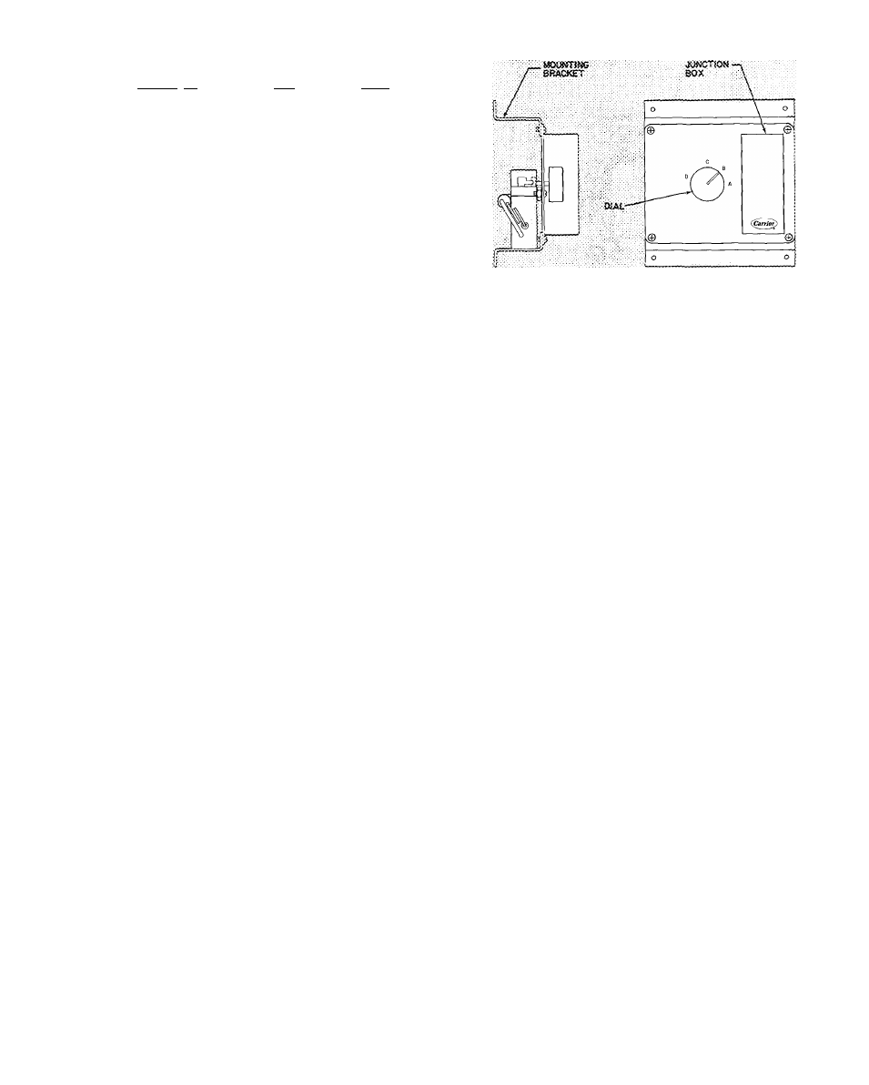
Table 6 — Air Quantity Limits
#
€
UNIT MODEL T
50DP0Ì2
50DP014
50DP016
MIN CFM
3000
3750
—4500
MAX CFM
5000
6250
7500‘
* Indoor Fan Max Watts = 3000
Automatic Changeover
— The unit automatically
switches from heating mode to cooling mode when
system selector switch is set at AUTO, and
temperature of the conditioned space rises to
cooling selector lever setting. When temperature of
the conditioned space falls to the heating selector
lever setting, unit automatically changes from
cooling mode to heating mode. The thermostat is
interlocked so that cooling and heating systems do
not operate at the same time.
Economizer Operation
— If unit is equipped with
modulating outdoor air control (economizer), it
should operate as follows:
ENTHALPY CONTROL SETTING ^ Set enthalpy
control (Fig. 12) to desired temperature and
relative humidity which provides cooling with
outside air only (no compressor operation). To
determine appropriate setting of enthalpy control;
1. Determine maximum combination of relative
humidity and temperature of supply air con
sidered acceptable for the installation.
2.
In Fig. 13, locate percent humidity on the
left-hand scale and dry-bulb temperature on the
right hand scale. Example in Fig. 13 uses 60%
RH and 66 F.
3. Draw a straight line connecting the 2 points.
4. Adjust the enthalpy control dial to the setting
indicated on control setting scale in Fig. 13.
The control setting for example conditions is
the B range.
MIXED AIR THERMOSTAT SETTING ^ Set
mixed air thermostat in return air compartment to
desired temperature of air delivered to the condi
tioned space (not less than 35 F or condensation in
unit will result). Do not uncoil mixed air thermo
stat capillary.
Cooling Season
When stage 1 is satisfied, outdoor fans, indoor
blowers and compressors shut off. Outdoor air
damper closes.
If fan switch is at ON, and stage 1 is satisfied,
outdoor air fans and compressors shut off, indoor
blowers continue to operate and outdoor air
damper stays in ventilation position.
INTERMEDIATE SEASON (Economizer Control)
— Operation is similar to cooling season except
when stage 1 of cooling thermostat closes, outdoor
air fans and compressor remain off if outdoor
enthalpy is below enthalpy control setting. Only
indoor blowers are operative. As temperature of
the mixed air (outdoor air mixed with return air)
rises above or drops below mixed air thermostat
setting, outdoor air damper modulates to maintain
mixed air setting.
Fig. 12 — Enthalpy Control Assembly
:Oi
20
-
I
-I
7g:v;3|
É
50-
Z
ui .
^'60^
IÜ
O;
70r
e>c
CONTROL
SETTING
% I
a:
o
s
80-
Fig. 13 — Nomograph for Determining
Enthalpy Control Setting
With the fan switch at AUTO, and the room
thermostat satisfied, indoor blowers shut off and
outdoor air damper closes. If fan switch is at ON
and room thermostat satisfied, damper goes to
ventilation position.
HEATING SEASON - Outdoor air damper always
stays in ventilation position while indoor blowers
are operating. The damper closes and the indoor
blowers shut off when the room thermostat is
satisfied.
-> Variable Volume Units
— Units suitable for use
with variable volume air handling systems are
equipped with 2 electric unloaders on the com
pressor. The control panel for these units (Fig. 14)
consists of a step controller, a proportional ther
mostat, a 7-day timer and a power switch.
Before starting unit, open compressor seiwice
valves and liquid line shutoff valve. Be sure com
pressor crankcase heaters have been on for 24 hours
and that crankcase oil level indicates half full.
-> Control Sequence Checkout
1. Turn on unit main power supply. Be sure unit is
ready to operate.
2. Set variable volume control panel POWER
switch at ON.