Carrier 50DP User Manual
Page 7
Attention! The text in this document has been recognized automatically. To view the original document, you can use the "Original mode".
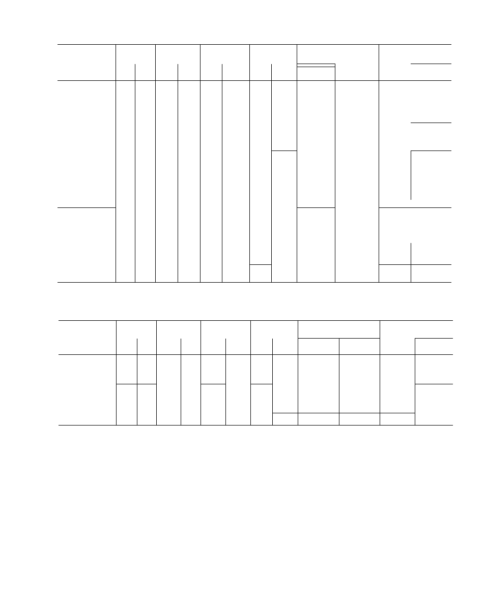
Table 3 — Electrical Data; 50DP014
VOLTS/PH/HZ
VOLTAGE
RANGE
COMPR
OUTDOOR
FAN MOTOR
INDOOR
FAN MOTOR
FACTORY INSTALLED
HEATERS
POWER SUPPLY
Min Ckt
Amps
Max Fuse
Amps
Min
Max
RLA
LRA
Qty
FLA
Hp
FLA
FLA
Nom Kw
2.0
7 4
__
80
90
3.0
8.4
—
—
80
90
2.0
7 4
39
18.8
80
90
2 0
7.4
72
34 2
100
LOO
200/3/60
180
220
27.0
160
2
4.6
2.0
2.0
7 4
7.4
117
156
56.1
74.8
160
205
150
200
3.0
8.4
39
18.8
80
■ ■■ ■ 90..
3.0
8.4
72
34.2
105
: 10
3.0
8.4
117
56 1
165
; 75
3 0
8.4
156
74 8
210
200
2.Ò
6.6
_
__
70
SO
3.0
8 4
-
-
70
8C'
2.0
6 6
47
18.8
70
:7L::::A8e.:A.;/
230/3/60
207
253
22.8
137
2
4 5
2 0
2 0
6.6
6.6
82
135
34 2
56 1
115
180
М М0 .
] 75
3 0
8.4
47
18.8
70
30 ■
3.0
8.4
82
34.2
120
DO
3.0
8.4
135
56.1
185
' / J
2 0
3.3
__
_
35
i 40
3.0
4.2
—
_
40
40
2.0
3 3
21
17.1
35
40
460/3/60
414
508
11.6
69
2
2.3
2.0
2 0
3.3
3.3
39
66
32.4
55 0
55
90
60
3 0
4 2
21
17.1
40
40
3.0
4.2
39
32.4
55
50
3.0
4.2
66
55 0
90
SO
575/3/60
518
632
9.3
55
2
1 8
2 0
3,0
2 3
3.8
-
-
30
30
30
Compr — Compressor
FLA — Full Load Amps
Hp — Horsepower
LRA — Locked Rotor Amps
RLA — Rated Load Amps
Fuse only; unshaded values indicate fuses or circuit
breakers
may be used
Table 4 — Electrical Data; 50DP016
VOLTS/PH/HZ
VOLTAGE
RANGE
COMPR
OUTDOOR
FAN MOTOR
INDOOR
FAN MOTOR
FACTORY INSTALLED
HEATERS
POWER SUPPLY*
Min
Max
RLA
LRA
Qty
FLA
Hp
FLA
FLA
Nom Kw
Min Ckt
Amps
Max Fuse
Amps
_
_
105
125
72-82
34.2
105-120
125
208-230/3/60
187
253
61.6
266
2
6.6
3
10.4
117-135
6.1
165-185
150-175
156-180
74.8
210-240
200-225
—
55
60
39
32.4
55
60
460/3/60
414
508
32
120
2
3.3
3
4.7
66
55.0
90
90
96
79.8
130
125
575/3/60
518
632
25.6
96
2
2.6
3
3 8
-
-
50
45
Compr
— Compressor
LRA
FLA
— Full Load Amps
RLA
Hp
— Horsepower
Locked Rotor Amps
Rated Load Amps
*Fuse only.
balanced within 10%. Contact local power com
pany for correction of improper voltage or phase
imbalance. Unit failure as a result of operation on
improper line voltage or excessive phase imbalance
constitutes abuse and may cause damage to elec
trical components. Such operation would invali
date applicable Carrier warranty.
Field Control Wiring
— Install a Carrier-approved
accessory thermostat assembly according to instal
lation instructions included with accessory. Locate
thermostat assembly on a solid wall in the condi
tioned space to sense average temperature.
Route thermostat cable or equivalent single
leads of no. 18 AWG colored wire from subbase
terminals thru conduit in unit to low-voltage
connections as shown on unit label wiring diagram
and in Fig. 11. Use no. 16 AWG wire for lengths
exceeding 50 feet. Set heat anticipator settings as
indicated in Table 5. Settings may be changed
slightly to provide a greater degree of comfort for a
particular installation.
Refer to accessory remote control panel in
structions as required.
Return Air Filters
— Check that correct filters are
installed in filter tracks. See Table 1. Do not
operate unit without return air filters.
Outdoor Air Inlet Screens
— Outdoor air inlet
screen(s) must be in place before operating unit.