Carrier 50DP User Manual
Page 10
Attention! The text in this document has been recognized automatically. To view the original document, you can use the "Original mode".
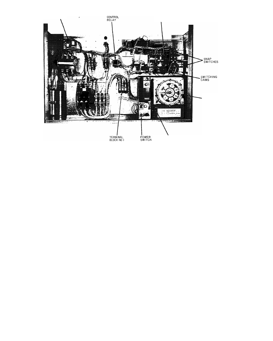
CYCLE-LOG
STEP
CONTROLLER
SEVEN
DAY
TIMER
PROPORTIONAL
THERMOSTAT
Fig. 14 — Control Panel, Variable Volume Units
3. If supply air leaving unit is above 50 F (or other
field-set temperature), step controller will oper
ate to de-energize compressor unloader solenoids
(compressor loads up) until set temperature is
achieved. An interval of 13.5 minutes is required
to maximum loading position. Refer to unit
label diagram for unloader sequencing. Also see
Fig. 15.
4. Step controller, 7-day timer and proportional
thermostat are factory set and adjusted. If other
settings or changes in adjustment are required,
refer to discussion of these items.
Seven-Day Timer Adjustment
— Factory settings
are ON —6:30 AM; OFF —7:30 PM for each of
7 days.
l . O n the timer dial face (Fig. 14), loosen the
thumbscrews which position the system ON and
OFF trippers.
2. Set trippers at desired system ON and OFF time
settings and tighten thumbscrews. Skipping a
day(s) is accomplished by removing trippers
from the dial.
3. Set the timer by turning the dial face clockwise
until fixed pointer indicates correct day and time.
Do not turn dial face counterclockwise. Do not
move fixed pointer.
■
Proportional Thermostat
— The proportional ther
mostat, Fig. 14, monitors temperature of the con
ditioned air leaving unit. On signal from the
thermostat, sequence motor operates cam switches
to load or unload compressor to maintain thermo
stat setting. Thermostat is factory set at 50 F ± 6 F
but may be reset between 0° F and 100 F as
follows:
TEMPERATURE SETTING - Turn knob on front
of case until pointer indicates desired set point
temperature. This is the center point of propor
tional range.
RANGE ADJUSTMENT — Remove cover and turn
adjustment wheel until pointer indicates desired
range.
If sequencer motor shaft constantly moves back
and forth, increase proportional thennostat range
(about 5 F" at a time) until system is stable.
^ Step Controller
— The step controller consists of a
reversible electric motor which drives a set of cams
that activate up to 5 snap-acting switches. Each
cam is adjustable to operate at any point on the
160 angular degrees of cam shaft rotation. The
differential of each switch may be adjusted from a
minimum of 5 angular degrees to a maximum
limited only by the 160 degrees of camshaft
rotation.
Rotational direction is controlled by the propor
tional thermostat thru the step controller feedback
potentiometer and balancing relay.
DETERMINING SWITCH SETTINGS - Switches
are factory set at angular settings as shown on
Fig. 15 (also shown on unit label diagram). To
reset, if desired, determine angular differential for
each switch and between switches. Then determine
minimum differential or throttling range of propor
tional thermostat to provide desired step controller
differential or throttling range. This range should
be wide enough to prevent rapid cycling from one
capacity step to another. Then adjust cams to new
settings as required.
t
10