Carrier 50DP User Manual
Page 5
Attention! The text in this document has been recognized automatically. To view the original document, you can use the "Original mode".
Outside Air Damper
(25% ventilation dir) -- Outside
air damper can be adjusted to permit up to 25%
outdoor air entry into return air compartment.
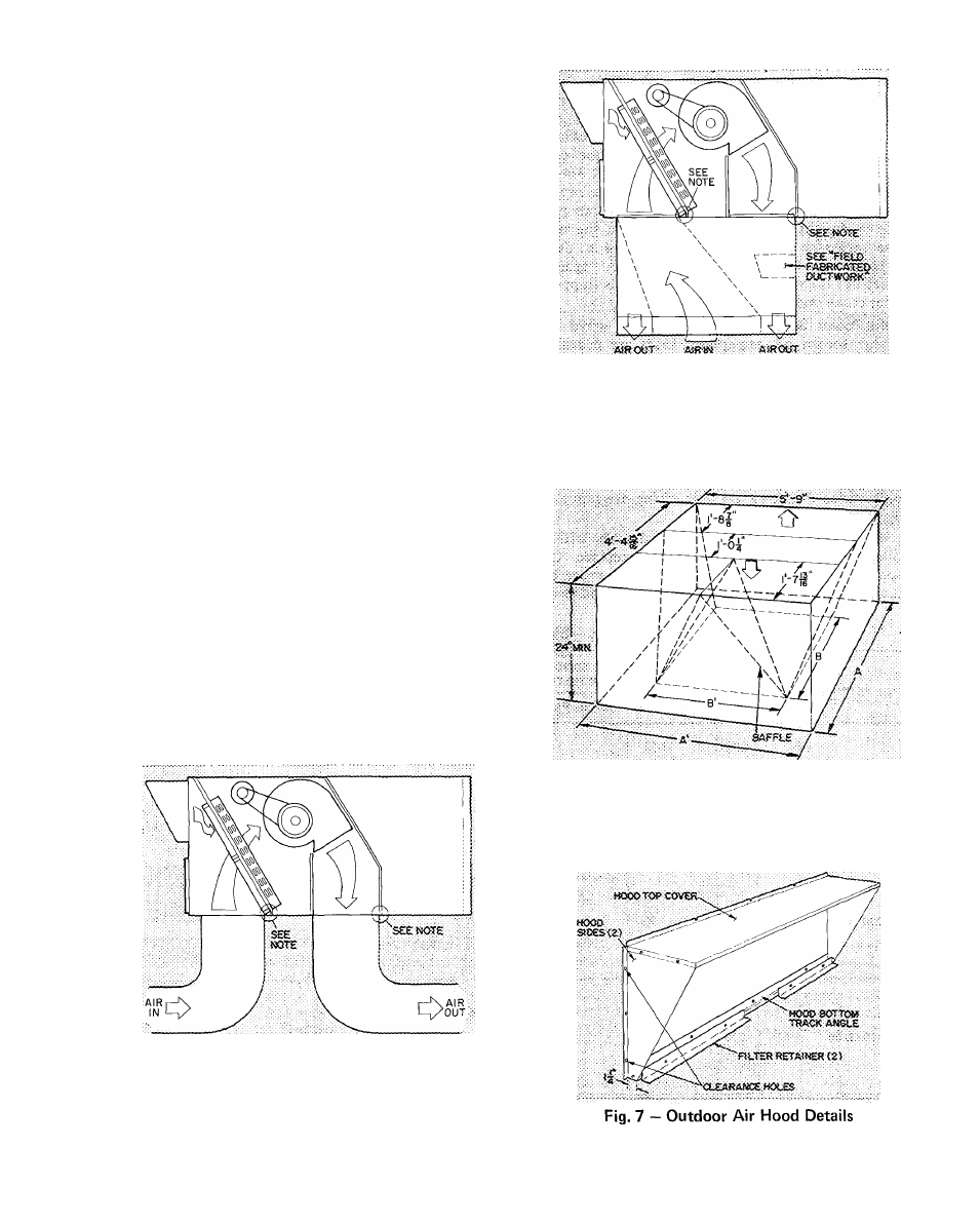
Outdoor Air Hood Installation
(Fig. 3) — The
outdoor air hood is common to 25% air ventilation
and economizer. The economizer and all electrical
connections are factory installed and adjusted. The
hood assembly, outdoor air inlet screen(s) and
required hardware are shipped in a carton located
on outdoor fan section and must be field installed.
Using screws in carton install hood as follows;
1. Assemble hood top cover, side panels and
bottom track angle (Fig. 7).
Loosen base unit top cover sheet metal screws
located above outdoor air inlet opening.
Match notches in hood top cover to unit top
cover screws. Insert hood flange between unit
top cover flange and unit. Tighten screws.
Secure hood sides and bottom track angle to
unit. The screw on unit that matches bottom
track angle center hole must be removed prior
to assembly. Re-use screw to secure bottom
track angle to unit.
Insert outdoor air filters and spacer in hood
filter tracks. NOTE: Hood may also be installed
by individually attaching hood parts to base
unit following sequence above.
6. Attach filter retainers to bottom track angle.
Indoor Blower
— Blower belts and pulleys are
factory installed. Belts are secured to pulleys with
tape. Remove tape and, if required, adjust as
described in Service, Indoor Blower Adjustment.
Condenser Air Fans and Motors
are factory set.
Refer to Service, Condenser Air Fan Adjustment as
required.
2
.
3.
4
5.
NOTE: Do not drill in this area, damage to basepan may result in
water leak
Fig. 5 — Concentric Duct Air Distribution
NOTE: Dimension A, A1 and B, B1 are obtained from field-supplied
ceiling diffuser
Fig. 6 — Concentric Duct Details
NOTE: Do not drill in this area, damage to basepan may result in
water leak
Fig. 4 — Air Distribution — Thru-the-Bottom