Service, Lubrication – Carrier 50DP User Manual
Page 11
Attention! The text in this document has been recognized automatically. To view the original document, you can use the "Original mode".
12
3
4
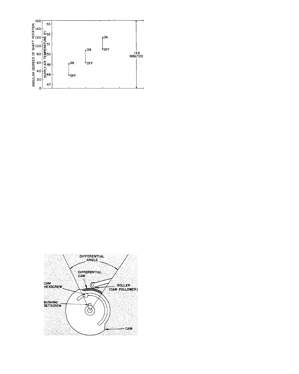
STEP CONTROL SWITCH
Fig. 15 — Step Controller Sequence
CAM ADJUSTMENTS - The step controller is
shipped with cams set to operate switches (i.e. com
pressor unloaders) as shown in Fig. 15. All switches
are closed (compressor unloaded). The shaft is
positioned all the way counterclockwise (as viewed
from motor end).
Using the following procedure, first adjust all
operating points in one direction of motor drive.
Then reverse motor direction and adjust switch
differentials. Use potentiometer wiper as an
approximate indicator of angular adjustments
using angular displacement scale mounted on
potentiometer back plate. Also see Fig. 16.
1. Loosen all bushing setscrews with a 1/16-in.
Allen wrench. Loosen all cam hex screws with
a 3/16-in. open-end wrench.
If setscrews are not accessible from top of con
troller, operate motor to rotate cams and
bushings by shorting terminals R and B for
counterclockwise rotation and terminals R and
W for clockwise rotation.
2. Momentarily de-energize motor to permit motor
to recycle to start position. Jumper terminals R
and W to run motor camshaft to desired position
MAKE
POIMT
St^EAX
POINT
Fig. 16 — Step Controller Cam Adjusting Details
(motor end view)
for operating first switch. "Stop motor in this
position by removing jumper between terminals
S and T.
3. Starting with first switch, turn cam clockwise
until switch makes an audible “click” as roller
moves up cam rise to higher level. This is the
operating point. Lock bushing setscrews.
4. Set operating point of each of remaining switches
in like manner. Advance motor by momentarily
jumpering terminals S and T.
5. Set switch differential by reversing motor (short
terminals R and B) and running it to desired
break point. Stop motor at this point by de
energizing power at LI (POWER switch off).
Start at last switch and progress to first switch.
Move differential cam clockwise so that roller
is on high part of cam. Be sure that switch is at
make position. To check this, manually lift
roller assembly to make switch. Move differential
cam counterclockwise until roller drops to low
level of cam. At this point switch should break.
Lock the hex screw.
6. Check settings by performing Control Sequence
Checkout.
7. If 115-volt to step controller is de-energized,
timer recycles to start point when power is
restored.
SERVICE
Cleaning
— Inspect unit interior at beginning of
each heating and cooling season or as operating
conditions require. Remove unit top panel and/or
side panels for access to unit interior.
EVAPORATOR COIL - Clean with Oakite 164 -
available from Carrier (Service Parts) under Part
No. 28GS680002.
CONDENSER COIL - Clean outdoor coil annually
or as required by location or outdoor air condi
tions. Inspect coil monthly — clean as required.
CONDENSATE DRAINS - Check and clean each
year at start of cooling season. In winter, keep
drains and traps dry or protect against freeze-up.
FILTERS — Clean or replace at start of each heat
ing and cooling season, or more often if operating
conditions require it. Refer to Table 1 for type
and size.
OUTDOOR AIR INLET SCREENS - Clean
screens with steam or hot water and a mild deter
gent. Do not use throwaway filters in place of
screens.
Lubrication
COMPRESSORS — Each compressor is charged
with correct amount of oil at the factory.
FAN SHAFT BEARINGS - No lubrication
required. Bearings are permanently lubricated.
FAN MOTOR BEARINGS - No lubrication of
outdoor fan or indoor blower motors are required
for first 5 years of operation. Annually thereafter,
clean and repack bearings with a suitable bearing
grease.
11