Start-up – Carrier 50DP User Manual
Page 8
Attention! The text in this document has been recognized automatically. To view the original document, you can use the "Original mode".
TBJ.
ao
o cc
O Ili
(/> a
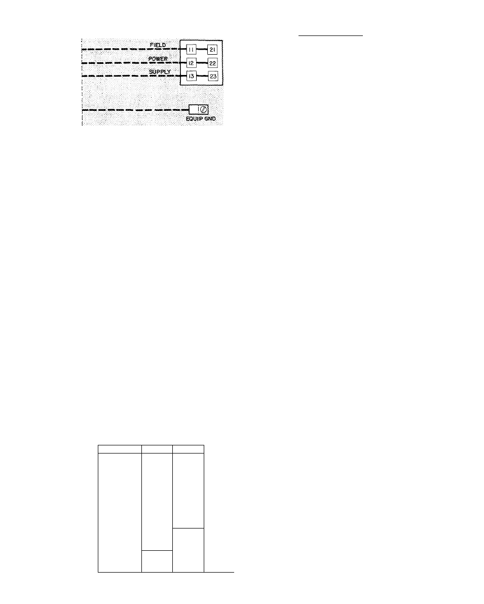
Fig. 10 — Field Power Wiring Connections
START-UP
Unit Preparation
— Make sure that unit has been
installed in accordance with installation instruc
tions and applicable codes.
Compressor Mounting
— On 50DP012/014 units,
compressors are internally spring mounted. Do not
loosen or remove compressor hold-down bolts. On
50DP016 units, loosen compressor hold-down
bolts until sidewise movement of the washer under
each hold-down bolt head can be obtained. Do not
loosen completely as bolts are self-locking and will
maintain adjustment.
Internal Wiring
— Check all electrical connections
in unit control boxes . . . tighten as required.
Refrigerant Service Valves
— Each 50DP012/014
unit system has 2 Schraeder type service ports, 1
on suction line and 1 on compressor discharge line.
Be sure that caps on the ports are tight. The
50DP016 has one service valve on suction line, one
on discharge line and one on liquid line. Be sure
valves are open.
Crankcase Heater(s)
are energized as long as there
is power to the unit. NOTE Unit power must be
on for 24 hrs. prior to startup
Table 5 — Heat Anticipator Settings
UNIT MODEL
50DP012/014
50DP016
VOLTAGES
KW
STAGE 1
STAGE 2
13
.26
_
200/3/60
23 8
39 1
.26
.52
26
26
52.0
52
52
17.3
.26
230/3/60
31 4
26
26
51 7
52
26
15.7
.26
_
460/3/60
29.8
.26
.26
50.5
.26
.52
23.8-31.4
.26
.52
208-230/3/60
39 0-51.7
52
.26
52.0-68.8
.52
.52
29.8
.26
.26
460/3/60
50 5
.26
.52
73.3
.52
.52
REMOVABLE JUMPER
rr°^
I
Ijji-i-g ® ^
^ [
g
]
THE RMOSTAT ASSEMBLY
' ¡H Й Й Й
[
g
]
и
Й'
Q
<
liJ
QH
I
^
3
O
>
CD
Z
_
DC
CD
CO
gJlW-VOLT^ TS^l^ 8upq<
Fig. 11 — Field Control Thermostat Wiring
Cooling
— To start unit, turn on main power
supply. Set system selector switch at COOL and
fan switch at AUTO. Set thermostat below room
temperature.
DP012 AND DP014
No. 1 compressor starts on closure of No. 1
contact in thermostat.
Additional rise in room temperature closes contact
No. 2 in thermostat, energizing No. 2 contactor.
Second compressor starts.
DP016
Compressor starts unloaded on closure of No. 1
contact in thermostat.
> Additional rise in room temperature closes contact
No. 2 in thermostat which de-energizes the unloader
coil. Compressor is now fully loaded.
Check cooling effects at a setting above room
temperature. Check unit charge. Refer to Refrig
eration Charge in Service Section.
Reset thermostat at a temperature above room
temperature. Compressor(s) will shut off.
TO SHUT OFF UNIT ^ Set system selector switch
at OFF position or reset thermostat above room
temperature. Units with Signal-LOC'^''^ protection
device shut down on any safety trip and thermo
stat light comes on. Determine reason for safety
trip. Restart 012/014 compressor by turning ther
mostat selector switch OFF then ON. Restart 016
compressor by resetting circuit breaker at unit.
Heating
— Turn on main power to unit. Set
thermostat at HEAT, fan at AUTO, and above
room temperature. First stage of electric heater
elements are energized on closing of heating
contact No. 1 in thermostat. On a further fall of
room temperature, heater contact No. 2 closes en
ergizing second stage electric heater elements.
TO SHUT OFF UNIT — Set system selector switch
at OFF.
HEAD PRESSURE CONTROL - All units have
fan cycling thermostats which, at 55 F, shut off
one outdoor fan motor. This permits unit to
operate down to 35 F outdoor air temperature.
Ventilating (Continuous Fan)
— Set fan and system
selector switches at ON and OFF, respectively.
Indoor air fans operate continuously to provide
constant air circulation.
I
i