Fig. 17 — indoor blower pulley adjustment, Fig. 18 — outdoor air fan adjustment – Carrier 50DP User Manual
Page 12
Attention! The text in this document has been recognized automatically. To view the original document, you can use the "Original mode".
his
lals
'ise
lier
the
lies
rily
ort
red
dé
fi).
i.
lier
1
at
lift
tial
ow
ak.
nce
,ed,
■ is
of
ing
/or
1 -
'art
illy
idi-
ich
îep
;at-
ing
фе
îan
ter-
of
»ed
ion
of
red
ter,
ing
Evaporator Blower Adjustrnent
— Blower motor
pulleys are factory set for speed shown in Table 1.
To change blower speed:
1. Shut off unit power supply.
2 Loosen belt by loosening blower motor mount
ing plate nuts.
3 Loosen movable pulley flange setscrew (see
Fig. 17).
4
Screw movable flange toward fixed flange to
increase speed and away from fixed flange to
decrease speed. Increasing blower speed in
creases load on motor. Do not exceed maximum
speed specified in Table 1.
See Table 6 for air quantity limits.
5. Set movable flange at nearest key way of pulley
hub and tighten setscrew. (See Table 1 for speed
change for each full turn of pulley flange.)
To align blower and motor pulleys, loosen
blower pulley setscrews and slide blower pulley
along blower shaft. Make angular alignment by
loosening motor from mounting plate.
MOVABLE
a.ANG£S
STRAIGHT EDGE
MOST BE
4WRAU£L
\VWTH8ELT f\
IsETSCREWsj^^'^l
SETSCREVVS
'ПХЕО FLANGES^
Si№LE-GROOve TVfO-GROOVE
MOTOR a FAR SHAFTS
MUST BE PARALLEL
Fig. 17 — Indoor Blower Pulley Adjustment
To Adjust Belt Tension
— Loosen blower motor
pivot bolts. Move motor mounting plate up or
down for proper belt tension (1/2-in. deflection
with one finger) and tighten pivot bolts. Adjust
lock bolt and nut on mounting plate to secure in
fixed position.
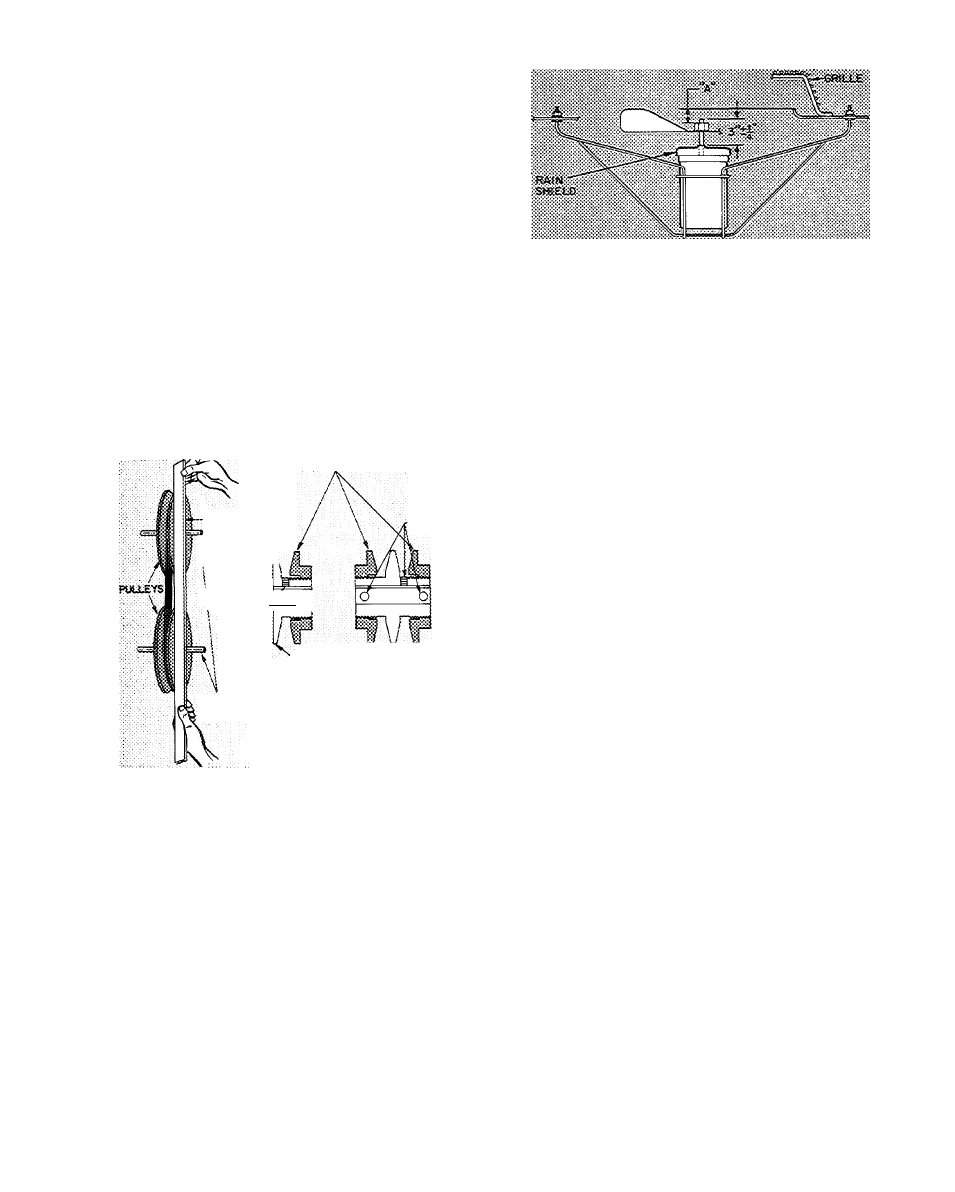
Outdoor Air Fan Adjustment
(Fig. 18) Shut off
unit power supply. Remove fan top grille assembly
and loosen fan hub screws. Adjust fan height on
unit using a straight edge placed across the fan
orifice. Tighten setscrews and replace rubber hub
cap to prevent hub from rusting to motor shaft.
Fill hub recess with permagum if rubber hubcap is
missing.
Economizer Adjustment
1. Set enthalpy control at its highest setting. If
outdoor temperature is above 70 F, perform
the following; install jumper between enthalpy
control terminals 1 and 2 (red and yellow wires).
Fig. 18 — Outdoor Air Fan Adjustment
2. Set system selector switch at COOL and set
cooling selector lever at lowest setting. (Cooling
mode may be simulated by removing thermostat
wires from terminals Y1 and Y2 [if used] and
installing jumper between Y1 and R.)
3. Set mixed air thermostat (MAT.) at lowest
setting. Outdoor air damper goes to fully open
position (indoor air damper closes).
4. Set mixed air thermostat at highest setting. Out
door air damper goes to fully closed position
(indoor air damper opens).
5. Adjust mechanical linkage for correct position
ing if necessary. If cooling was simulated in 2,
remove jumper and reconnect thermostat wire(s).
DAMPER VENT POSITION SETTING
1. Set fan switch at ON (continuous fan operation)
and close niglit switch if used.
2. Set system selector switch at OFF.
3. Remove cap from vent adjustment screw on
damper motor terminal box cover.
4. Turn adjustment screw slowly until dampers
assume desired vent position. Do not manually
operate damper motor. Damper to motor will
result.
POWER FAILURE — Dampers do not have a
spring return. In event of power failure, dampers
remain in position until power is restored. Do not
manually operate damper motor.
Refrigerant Charge
— Amount of refrigerant charge
is listed on unit nameplate (also refer to Table 1).
Refer to Carrier Standard Service Techniques
Manual, Chapter 1, Refrigerants.
Unit panels must be in place when unit is
operating during charging procedure.
NO CHARGE — Use standard evacuating tech
niques. After evacuating system, weigh in the
specified amount of refrigerant. (Refer to Table 1.)
LOW CHARGE COOLING — Using appropriate
cooling charging chart. Fig. 19, 20 or 21 add refrig
erant until conditions of the chart are met. Note
that charging charts are different from ones nor
mally used. Charts are based on charging units to
12