Carrier 50DP User Manual
Page 6
Attention! The text in this document has been recognized automatically. To view the original document, you can use the "Original mode".
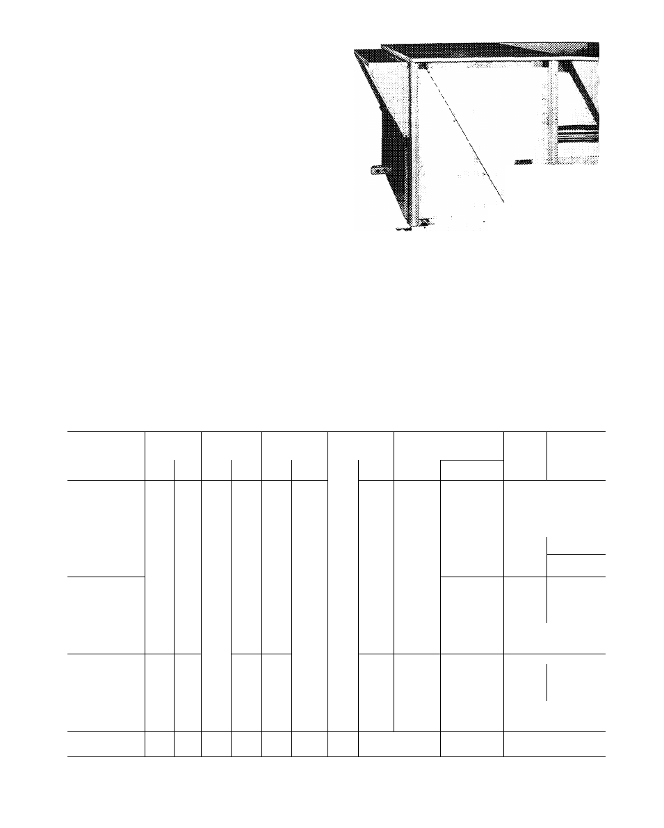
Condensate Drain
— See Fig. 3 and 8 for drain
locations. Plugs are provided in both drain holes
and at least one must be removed when unit is
operating. Two 3/4-in. half couplings are provided
inside the unit evaporator section for the con
densate drain connection(s). An 8 1/2-in. x 3/4-in.
diameter and 2 in. x 3/4-in. diameter pipe nipple
coupled to standard 3/4-in. diameter elbows pro
vide a straight path down thru holes in the unit
base rails (see Fig. 9). A trap at least 4 in. deep
must be used and must be protected against
freeze-up. If only one drain connection is trapped,
other connection must be plugged.
Field Power Supply
— Unit is factory wired for
voltage shown on nameplate. Units are provided
with terminal block.
When installing units, provide a disconnect per
NEC of adequate size. (Table 2, 3, 4.)
All field wiring must comply with National
Electrical Code and local requirements.
Route power lines thru control box end panel
— or unit basepan — (Fig. 3) to terminal
connections as shown on unit wiring diagram and
Fig. 10.
Operating voltage to compressor must be within
voltage range indicated on unit nameplate. On
3-phase units, voltages between phases must be
balanced within 2% and the current must be
drain
i|
drain
hole
CONNECTION (BOTH SIDES)
Fig. 8 — Condensate Drain Details
3'ppT
* rSAÌWCOKfiECTlOÌ'ÌU_____
(HAt.fCOyPt.iSSi p i
r
SASEftfiit.
r
I
TO TRAP
•5'
Fig. 9 — Condensate Drain Piping Details
f
Table 2 — Electrical Data; 50DP012
VOLTS/PH/HZ
VOLTAGE
RANGE
COMPR
OUTDOOR
FAN MOTOR
INDOOR
FAN MOTOR
FACTORY INSTALLED
HEATERS
POWER
Min Ckt
Amps
SUPPLY
Max Fuse
Amps
Min
Max
RLA
LRA
Qty
FLA
Hp
FLA
FLA
Nom Kw
1
3 45
_
70
70
1.5
5.5
—
-
-
70
7$
1
3 45
39
18.8
70
70
1
3.45
72
34 2
100
90
200/3/60
1
3 45
117
56.1
155
1 oO
180
220
24
113
2
4 6
1
3.45
156
74.8
205
175
1.5
5.5
39
18.8
70
• ••
1.5
5.5
72
34.2
100
9>3
1.5
5.5
117
56.1
155
150
1.5
5.5
156
74.8
205
175
1
3.2
—
-
60
1.5
5.1
—
60
1
3.2
47
18.8
65
70
230/3/60
207
253
20.9
98
2
3.8
1
1
3.2
3 2
82
135
34 2
56.1
1 10
180
..........
1.5
5.1
47
18.8
65
' 70'
1 5
5.1
82
34 2
110
no
1.5
5.1
135
56.1
180
i
7
d
1
1.6
_
—
30
35
1.5
2.Ó
—
-
35
35
1
1.6
21
17.1
30
3S
49
2.1
1
1 Ó
39
32.4
55
50
460/3/60
414
508
10.5
2
1
1.6
66
55 0
85
30
1 5
2.6
21
17.1
35
3S
1.5
2.6
39
32.4
55
50
1.5
2.6
66
55.5
90
30
575/3/60
518
632
8.3
41
2
1.8
1
1 5
1 35
1 7
“
-
25
25
25
2.5
Compr
—
Compressor
FLA — Full Load Amps
Hp
—
Horsepower
LRA
RLA
—
Locked Rotor Amps
— Rated Load Amps
•
.
1
Fuse only; unshaded values indicate fuses or circuit breakers
may be used
«