Caafsoi be, Compressor removal — 50qt112, 115, 118, Coupi.{(«5aocif – Carrier 50QT User Manual
Page 9
Attention! The text in this document has been recognized automatically. To view the original document, you can use the "Original mode".
#
AccuRater™
Device
(Dual-Piston
Type)
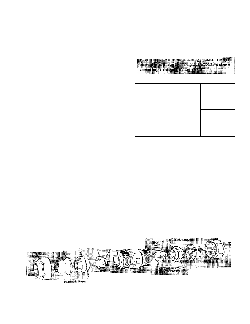
Servicing — See Fig. 15 for dual-piston AccuRater
components. The pistons have a refrigerant meter
ing orifice through them. The retainers form a stop
for the pistons in the refrigerant bypass mode, and
a sealing surface for liquid line flare connection.
To clean or replace piston;
1. Shut off power to unit.
2.
Protect area around unit to prevent damage to
interior, furnishings, etc.
3. Remove refrigerant from unit.
4.
Remove liquid line flare connections from
AccuRater. See Fig. 3 for AccuRater location.
5. Note position of arrow on AccuRater body in
relation to unit.
6.
Pull retainer out of body. Be careful not to
scratch flare sealing surface. If retainer does not
pull out easily, carefully use locking pliers to
remove retainer. Replace scratched or damaged
retainer.
7. Slide piston out by in.serting a small soft wire
through
metering
hole
(18-gage
thermostat
wire). Check that metering hole, sealing surface
around
piston
cones and
fluted
portion of
piston are not damaged.
8. See chart on indoor blower scroll for illustration
of proper arrangement and sizes of pistons.
9. Clean piston refrigerant metering orifice.
10.
Replace retainer O-ring before reassembling
AccuRater.
Carrier
O-ring
Part
No.
is
99CC501052.
LIQUID LINE STRAINERS (protect AccuRater),
are made of wire mesh and located in the liquid line
on each side of the AccuRater. The strainers are
pressed into the line. Remove strainer by threading
a #10 sheet metal screw into strainer and pulling
the screw with pliers.
Compressor Removal — (Refer to Fig. 2.)
caafsoi
be
xaoVfiiS fmm aa btsislied cfesssis* Rmove
fnbi» sleeve, feratg. io &eTvice ijttcfe
or deales' sJiojr T^efore retaoviag coiap-ressor.
See Table 3 for compressor information. Follow
safety codes and wear safety glasses and work
gloves. Have quenching cloth available.
Table 3 — Compressor Data
UNIT 50QT
CONIPRESSOR
OIL RECHARGE
(oz)
112
Copeland
RE-Z30150-PFV
20
115
Tecumseh
AB5515H
32
118
Copeland
CRB1-0175 PFV
51
124
Copeland
CRD-10200-PFV
51
130
Copeland
CRF1-0250-PFV
51
Compressor Removal — 50QT112, 115, 118
1. Shut off power to unit. Remove chassis indoor
cover, Fig. 1.
2. Remove chassis to truck or shop.
3.
Remove refrigerant from unit using refrigerant
removal methods described in Carrier Standard
Service
Techniques
Manual,
Chapter
I,
Refrigerants.
4.
Remove core from suction and discharge line
Schrader valves.
5. Remove compressor guard.
#
mr
CQCSL»i&
coociweEssTOii
iOQiTirtCATiOM
'50
(«BOOR
TO
COOytiiS STA»P££f
coupi.{(«5aocif ,
STRiawes
i«>T£.
are too&iec « s i d e c i P A c c v R i a w
ssi cosi>t>0oeRt& ¡s ««(cai-fijr
correct
Fig. 15 — AccuRater Device (Dual-Piston) Components