Step 3 — install thermostat and connect, Fig. 2 — outdoor component location – Carrier 50QT User Manual
Page 3
Attention! The text in this document has been recognized automatically. To view the original document, you can use the "Original mode".
Step 2 — Install Chassis in Wall Sleeve —
Remove sleeve filler panel and save screws. Install
outdoor grille using these screws. Remove indoor
plastic wrapper as described in Step 1. Do not
handle cha.ssis with plastic wrapper in place.
SLIDE CHASSIS INTO SLEEVE — Chassis is
heavy. Portable lifting device must be used. Exercise
caution to make sure forks do not damage chassis
components
(such
as
drain
connections)
while
lifting and installing. Guide chassis into sleeve on
indoor side by first placing chassis guide channels
onto sleeve guide channels at bottom of sleeve.
Slide chassis into sleeve until center partition peri
meter meets gasket provided around outer edge of
sleeve.
Check electrical
plugs
for alignment as
chassis is slid into place.
Tighten chassis into place by driving 6 screws,
provided in separate bag with chassis, into nuts
provided on sleeve (see Fig. 3).
Electrical and condensate drain connections are
complete when chassis is installed correctly into
sleeve.
Step 3 — Install Thermostat and Connect
Thermostat Wiring — (Thermostat and subbase
are packaged separately with unit shipment.)
Thermostat can be installed in 50QT or in remote
location.
TO MOUNT THERMOSTAT IN UNIT;
1. Remove metal cover plate by removing 6 screws.
2.
Locate and install subbase onto thermostat
bracket running between right and left coil par
tition (see Fig. 3). Push plug and wires through
hole provided.
3.
Connect plug from subbase to mating socket
located on left coil partition (see Fig. 3).
4.
Attach thermostat to subbase and snap on
thermostat cover.
5. Cut hole in stenciled area on back side of wrapper
with a sharp utility knife.
6.
Cut and remove insulation from hole in metal
cover plate.
7. Replace metal cover plate.
TO MOUNT THERMOSTAT REMOTELY:
1.
Pull subbase extension cord, previously installed,
up into the return air inlet. Plug cord into mating
socket on the left-hand coil partition. (See Fig. 3.)
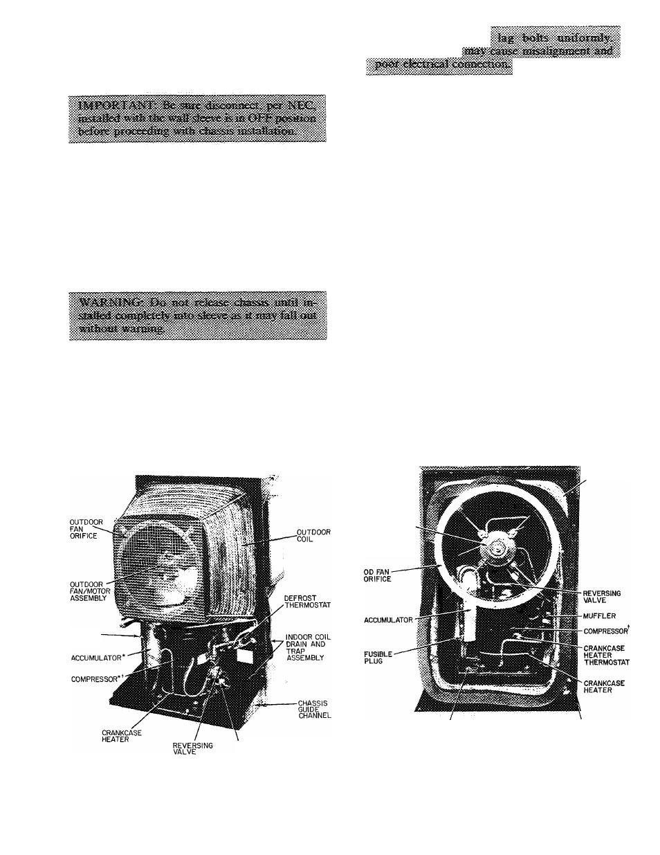
OUTDOOR
COIL
FUSIBLE-
PLUG
CRANKCASE HEATER
THERMOSTAT
50QT112, 115, 118
^Accumulator and compressor location reversed on 50QT112
tCompressor guard removed
00 FAN MOTOR
(PROPELLER
FAN REMOVED
TO SHOW
MOTOR)
COMPRESSOR MOUNTING
PAN
CHASSIS GUIDE
CHANNEL
50QT124, 130
^Outdoor fan guard and compressor guard removed to show
components
Fig. 2 — Outdoor Component Location