Fig. 3 — indoor component location, Cold climate accessory, Start-up – Carrier 50QT User Manual
Page 4: Service
Attention! The text in this document has been recognized automatically. To view the original document, you can use the "Original mode".
ACCURATER
LOCATION
MAIN
CONTROL BOX
COVER
ELECTRIC HEATER
CONTROL BOX COVER
MATING
SOCKET
LOCATION
INDOOR NAMEPLATE
LOCATION
CHASSIS
MOUNTING
BOLTS
(6 TOTAL)
THERMOSTAT
MOUNTING BRACKET
50QT112,115,118
SLEEVE
ELECTRIC HEATER
JUNCTION
LOCATION
BOX ACCESS
PLATE
MAIN
CONTROL
BOX
(SLIDES OUT
FOR
servicing
:
CENTER
PARTITION
INDOOR COIL
CONDENSATE
DRAIN
LEFT COIL PARTITION
INDOOR NAMEPLATE LOCATION
ELECTRIC HEATER COVER
./INDOOR FAN
MOTOR
(NOT VISIBLE)
DEFROST
/THERMOSTAT ON
LIQUID LINE
LOW-PRESSURE
SWITCH
v(NOT SHOWN)
^COMPRESSOR
SUCTION
SERVICE PORT
BRIGHT COIL
■ PARTITION
ROOM THERMOSTAT
(CAN BE MOUNTED
REMOTELY)
INDOOR AIR FILTER
THERMOSTAT PLUG
50QT124,130
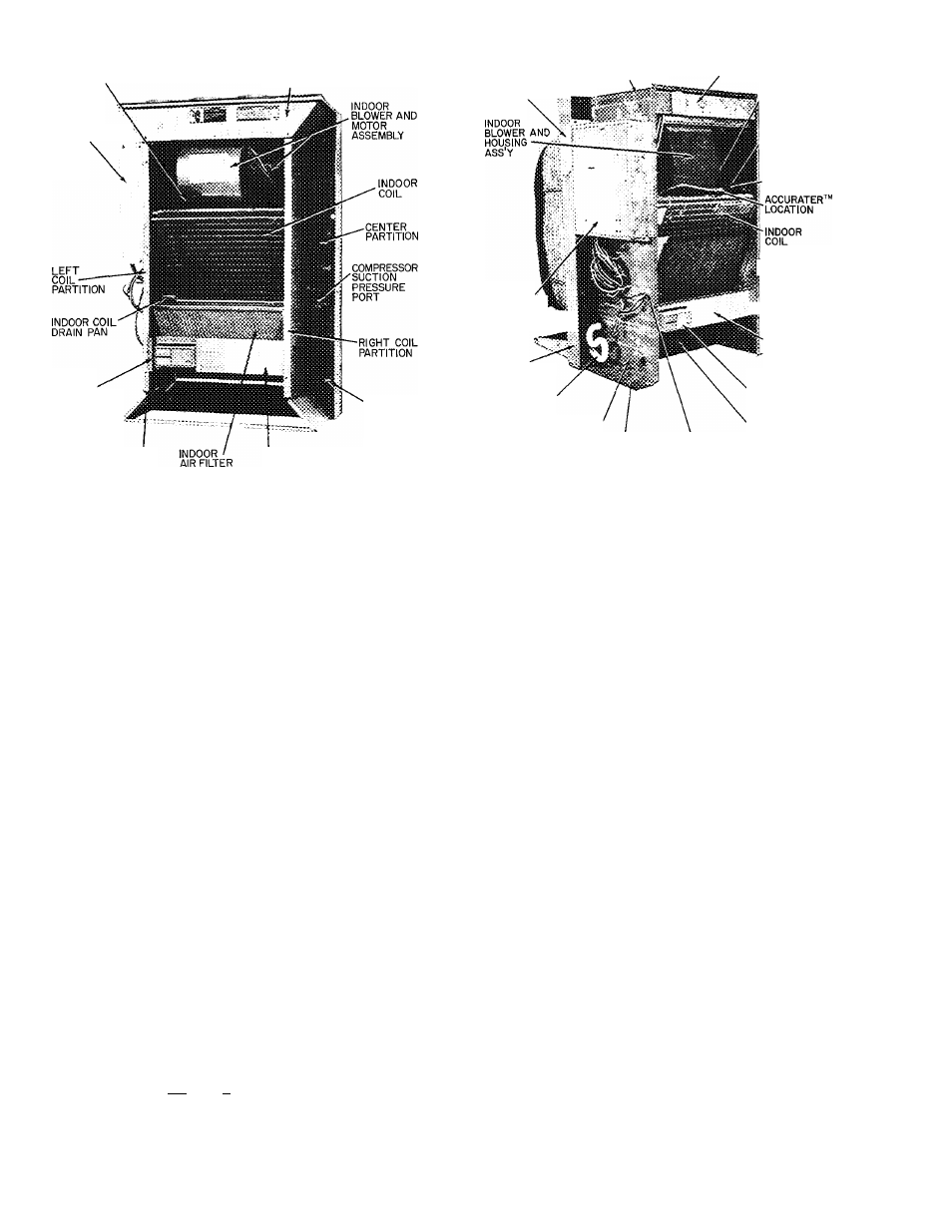
Fig. 3 — Indoor Component Location
2. Plug other end of cord, hanging from the wall at
its remote location, securely into subbase.
3. Push plug and excess leads into wall hole. Cover
hole appropriately to avoid incorrect thermostat
readings.
4. Mount subbase onto wall.
5.
Attach thermostat to subbase. Snap on cover
and install chassis indoor cover.
>
COLD CLIMATE ACCESSORY
Cold climate accessory should be installed on
50QT100 units where the outdoor ambient tem
perature consistently falls below 30 F. Cold climate
accessory is available in both six packs and single
packs as indicated below: for 50QT112, 115, 118 —
accessory part no. 50QT90016106 (six pack) or
50QT900160 (single pack); for 50QT124, 130 —
accessory part no. 50QT90017106 (six pack) or
50QT900170 (single pack).
START-UP
Crankcase Heater — The 50QT compressor is
equipped with a crankcase heater that is thermo
statically activated in cold weather. (See Fig. 2 and
3.) If temperature is below 65 F, operate crankcase
heater 24 hours before starting unit. To energize
crankcase heater only, after chassis installation, set
thermostat to
power at disconnect switch.
Thermostat
Anticipator
—
Room
thermostat
anticipator settings for all 50QT heat pumps is
0.20 amps. This setting may be changed slightly to
provide a greater degree of comfort fora particular
installation.
To Start Unit — Check that main power is on and,
if temperature is below 65 F, that compressor
crankcase heater has been energized for at least
24 hours.
1. Set selector switch at*C •
2. Set fan switch as desired (FAN) (AUTO.).
3. Set thermostat lever at the desired temperature.
4.
Set selector switch at HEAT or COOL. Check
system
refrigerant
charge.
See
Refrigerant
Charging.
SERVICE
Low-Pressure Switch (Safety Control) is lo
cated on liquid line downstream of AccuRater™
control during cooling mode (or upstream of Accu
Rater control during heating mode). Switch opens
at 5 psig and shuts down compressor to protect it
from overheating if refrigerant charge is too low.
High and low side pressure connections are acces
sible from the incloor portion of the unit for
charging. (See Fig. 3.)
High-Pressure Relief Valve (Safety Control) is
located in compressor. Relief valve opens at a pres
sure differential of approximately 450 ± 50 psi
between suction (low side) and discharge (high side)
to allow pressure equalization.
Internal
Current
and
Temperature
Sensitive
Overload (Safety Control) re.sets automatically
when compressor motor temperature drops to a safe
level (overloads may require up to one hour to reset).
#