Refrigerant charging, Catltiof^; to pfeveat persotial fejury. 'wear, Safeij; giasoe» ao<3 giovfes ha»d3t»g – Carrier 50QT User Manual
Page 5
Attention! The text in this document has been recognized automatically. To view the original document, you can use the "Original mode".
#
When an internal overload is suspected of being
open, check by using an ohmmeter or continuity
tester.
If
necessary,
refer
to
Carrier
Standard
Service Techniques Manual, Chapter 2, Electrical,
for complete instructions.
Defrost Control, consisting of a defrost timer,
defrost
thermostat
and
defrost
relay,
interrupts
normal system heating operation to remove frost
and ice formation on outdoor coil. Frost impairs
unit
performance.
Defrost
control
simultaneously
stops outdoor fan, energizes reversing valve sole
noid to switch system into cooling cycle (outdoor
unit
as
condenser,
indoor
unit
as
evaporator),
and
activates
electric
heater.
Unit
can
defrost
every 90 minutes, but will do so only if outdoor
temperatures are in the frosting temperature zone.
For heat pump to defrost, 2 conditions are
necessary:
1. Defrost timer contacts must be closed.
2. Coil temperature must be cold enough to cause
defrost thermostat contacts to close.
Contacts close at 28 ±3 F (50QT112 - 118) and
35 ± 3 F (50QT124, 130). Every 90 minutes of
elapsed running time, the defrost timer contacts
close for 10 seconds. If the defrost thermostat
contacts are closed, the unit defrosts. The defrost
timer
limits
defrosting
period
to
10
minutes.
Normally the frost is removed and the defrost ther
mostat contacts will open to terminate defrosting
before 10 minutes have elapsed. Defrost thermostat
contacts open at 65 ±5F (50QT112 - 118) and
75
±5F
(50QT124,130).
When
defrosting
is
terminated, the outdoor fan motor is energized
and reversing valve solenoid is de-energized, re
turning unit to heating cycle.
HEAT PUMP CIRCUITS shown in Fig. 4 are
refrigerant flow diagrams for heating and cooling
cycles.
Refrigerant Charging
CAtlTiOf^; To pfeveat persotial fejury. 'wear
safeij; giasoe» ao<3 giovfes
ha»d3t»g
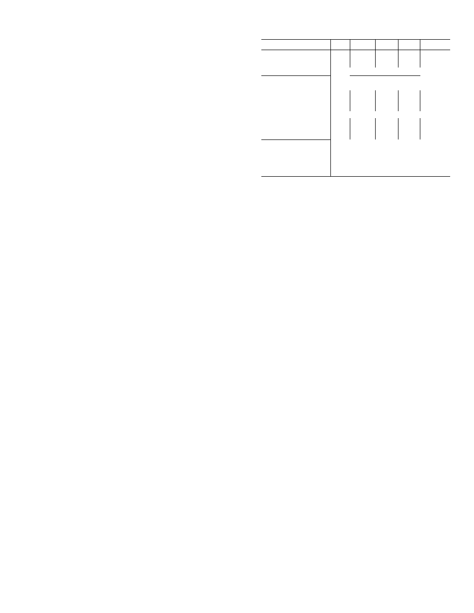
Table 2 — Service Data
Do not overcharge system. An overcharge can
cause compressor flooding.
Unit refrigerant system is factory charged. When
recharging is necessary, weigh in total charge indi
cated in Table 2. (Charge must be weighed in during
heating season.) Remove any refrigerant remaining
in system before recharging. If system has lost com
plete charge, triple-evacuate system to 5000 microns
(29.7 in. vacuum) before recharging. Service port
connections are provided on unit suction and dis
charge lines for evacuation and charging. (See Fig. 4
for service port location.) Dial-a-charge charging
cylinder is an accurate device used to recharge
systems by weight. These cylinders are available at
refrigeration supply firms.
UI\IIT50QT
112
115
118
124
130
MODEL
300
300
300
300
300
R-22 CHARGE* (lb)
2 7
2 7
3 2
4 5
47
Refrig Control
AccuRater™ Bypass Type
INDOOR FAN
Centrifugal Blower,
Direct Drive, 2-Speed
Rotationt
CW
CW
CW
CCW
CCW
Rpm
1580
1550
1570
1675
1675
Diameter (in )
6
6
6
7
7
Width (in.)
8
430/
550/
575/
885/
1025/
Range (cfm)
375
475
480
800
960
Motor Hp
'A
'A
Vs.
'/4
V4
OUTDOOR FAN
Propeller, Direct Drive, Single Speed
Cfm
1700
1700
1700
2000
2000
Rpm
1125
Diameter (in )
15
Motor Hp
Vs
ccw
cw
Counterclockwise
Clockwise
‘Factory
refrigerant
charge
fLooking at fan motor shaft
To check and/or adjust charge during cooling
season, use Cooling Cycle Charging Charts (Fig. 5,
7, 9, II, 13) and follow Charging Chart Method
below. The charging chart may also be used as an
alternate method of recharging system.
To check
system operation
during heating cycle,
use Heating Cycle Operation Check Chart (Fig. 6, 8,
10, 12, 14). These charts indicate whether a correct
relationship exists between system operating pres
sures and air temperatures entering unit. If pressure
and temperature lines do not intersect on chart,
the system refrigerant charge may not be correct
or other system abnormalities may exist. Do not
use Operating Check Charts to adjust refrigerant
charge. Weigh charge into system.
COOLING CYCLE CHARGING CHART
METHOD
1. Operate unit a minimum of 10 minutes before
checking charge, and after each charge
adjustment.
2. Measure suction pressure by attaching a gage to
unit suction service port. (See Fig. 4 for correct
service port location.)
3. Measure outdoor (coil inlet) air dry-bulb tem
perature. Use service thermometer.
4. Using a sling psychrometer, measure wet-bulb
temperature of air entering indoor fan coil.
5. Refer to Charging Chart. Locate on curves where
outdoor air dry-bulb and indoor air wet-bulb
temperature lines intersect.
6.
From intersect point, project vertically down
ward to chart suction pressure line. Compare
chart suction pressure to unit suction pressure
(Step 2).
7. If unit suction pressure is lower than chart pres
sure,
add
refrigerant
to
system
until
chart
pressure is reached. If unit suction pressure is
higher than chart pressure, remove refrigerant
until chart pressure is reached.