Carrier 50QT User Manual
Page 12
Attention! The text in this document has been recognized automatically. To view the original document, you can use the "Original mode".
6.
Make sure condensate pan drain is not clogged
with debris.
7. Reinstall chassis in sleeve.
8. Restore power to unit.
Indoor Coil and Condensate Pan Cleaning —
Clean and inspect indoor coil, condensate pan and
drain at same time outdoor coil is cleaned.
1.
Use vacuum cleaner nozzle to clean the face
of coil.
2.
Clean condensate pan with a brush similar to
that shown.
3.
Hold pail under condensate pan drain connec
tion and flush pan by slowly pouring water on
coil. Do not overflow pan.
Indoor Air Filter Replacement (Refer to Fig. 3.)
— Replace filters at least 4 times per year especially
at the beginning of the heating and cooling seasons.
On 50QT112, 115 and 118, slide filter through
slots at bottom of left and right coil partitions.
Slide filter upward until top of filter reaches top of
filter brackets. Then, rest bottom of filter on
bottom flanges of left and right coil partitions.
On 50QT124 and 130, slide filter upward until
top of filter reaches top of filter brackets. Then,
rest bottom of filter on horizontal sheet metal shelf
between left and right coil partitions making sure
tabs at bottom of filter brackets hold filter in place.
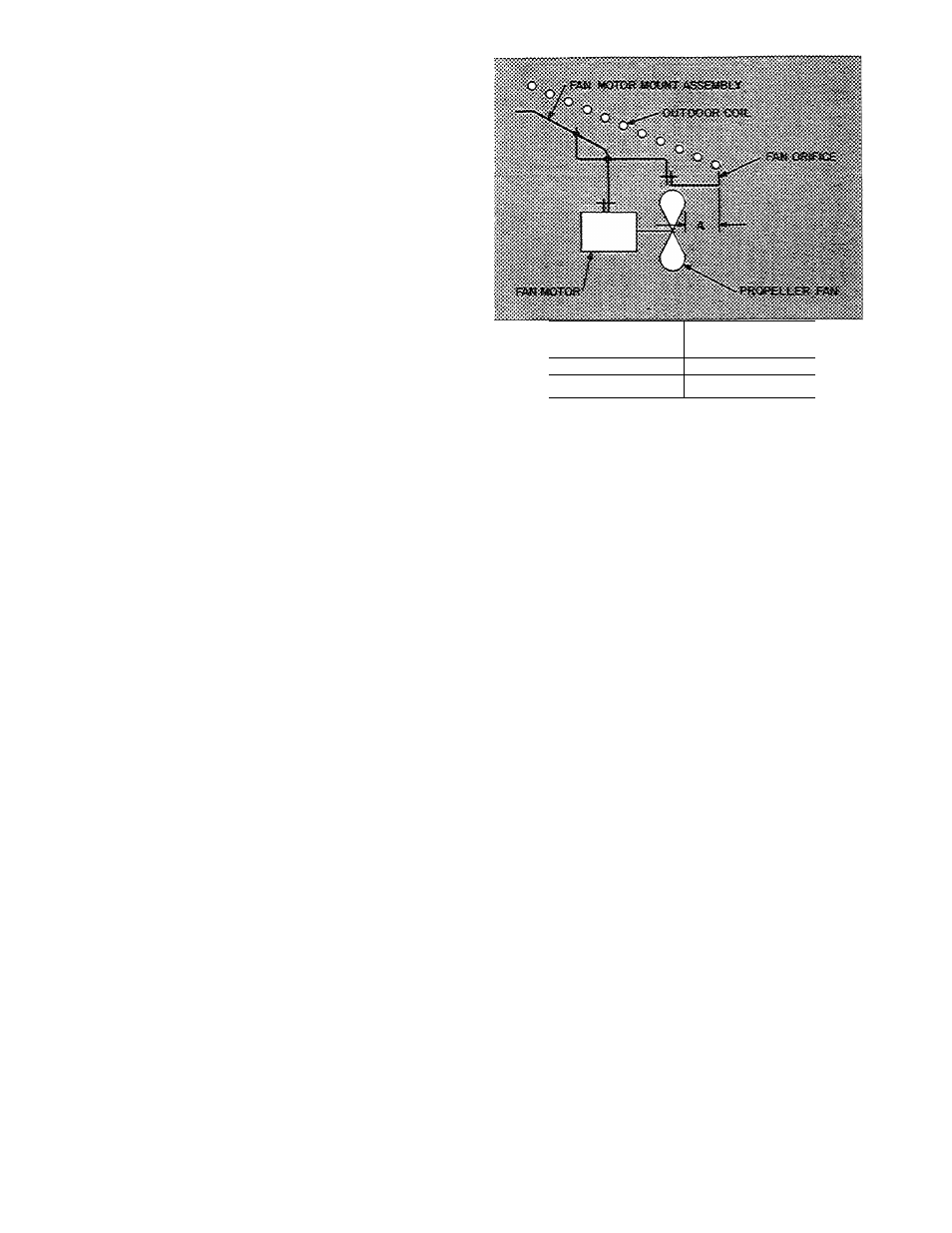
Outdoor Fan Adjustment — Required fan posi
tion is shown in Fig. 18. Adjust position by loosen
ing setscrew on fan hub and moving in or out of
orifice.
Outdoor Fan/Motor Removal
1. Shut off power to unit.
2.
Remove chassis from sleeve as described pre
viously in Outdoor Coil Cleaning section.
UNIT 50QT
DIMENSION A
(in.)
112, 115, 118
2V2
124, 130
2
Fig. 18 — Outdoor Fan Position
4.
Remove 4 nuts from outer tip of coil support
rods and remove wire mesh guard.
Remove fan blade from motor shaft by loosening
hub setscrews and slipping it off shaft.
5.
Remove fan motor leads from electrical com
ponents in indoor side control box and pull
through bulkhead so they are loose in outdoor
machine compartment.
6.
Remove nuts and bolts connecting 4 motor ears
to motor support struts.
7. Remove motor and leads.
8.
Reassembly is reverse of above procedure. Make
sure guard is replaced and fan is positioned
correctly as in Fig. 2.
12