Table 2 — electrical data – Carrier 50DP016 User Manual
Page 8
Attention! The text in this document has been recognized automatically. To view the original document, you can use the "Original mode".
25%
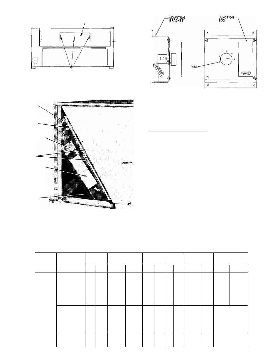
ADJUSTABLE
AIR DAMPER
BASE
'UNIT
SECURING SCREWS
Fig. 12 — 25% Outdoor Air Section Details
COOLING
LOCKOUT
SWITCH
ENTHALPY
CONTROL
DAMPER MOTOR
FILTERS
ECONOMIZER
CONTROL BOX
ECONOMIZER
::|i
Fig. 13 — Enthalpy Control Location
(Economizer Damper Assembly — End View)
Fig. 14 — Enthalpy Control Assembly
Mixed Air Thermostat Setting — Set mixed air thermo
stat in return air compartment to desired temperature of
air delivered to the conditioned space (not less than 35 F
or condensation in unit will result).
Damper Vent Position Setting
1. Set fan switch at ON (continuous fan operation) and
close night switch if used.
2. Set system selector switch to OFF.
3. Remove cap from vent adjustment screw on damper
motor terminal box cover.
4. Turn adjustment screw slowly until dampers assume
desired vent position.
Do not manually operate
damper motor; damage to motor will result.
Table 2 — Electrical Data
UNIT
MODEL
VOLTS-PH-HZ
VOLTAGE
RANGE
COMPR
OUTDOOR
FAN
MOTOR
INDOOR
FAN
MOTOR
FACTORY-
INSTALLED
HEATERS
POWER
SUPPLY
Min
Max
RLA
LRA
Qty
FLA
Hp
FLA
FLA
kW
Min Ckt
Amps
MOCP
(Amps)
50DP012
208/230-3-60
187
253
24 0
(ea)
136
(ea)
2
38
1 0
1 5
1 0
1 0
1 0
1 0
1 5
1 5
1 5
1 5
40
5 7
40
40
40
40
5 7
5 7
57
5 7
74/ 82
122
122/135
41/ 45
74/ 82
122
122/135
41/ 45
26/31
42*
42/52
14/17
26/31
42*
42/52
14/17
66/ 66
68/ 68
98/108
158
158/174
66/ 66
101/110
160
160/176
68/ 68
175
460-3-60
414
508
105
(ea)
49
(ea)
2
25
1 0
1 5
1 0
1 0
1 0
1 5
1 5
1 5
1 8
2 6
1 8
1 8
1 8
26
26
26
21
39
66
21
39
66
16
30
51
16
30
51
31
i ta
575-3-60
518
632
8 3
(ea)
41
(ea)
2
2 1
1 0
20
1 0
20
1 4
27
1 4
2 7
37
37
37
37
23
1 30
24
30
48
50
50 50
i