Step 6 — make electrical connections, Step 7 — make outdoor air inlet adjustments – Carrier 50DP016 User Manual
Page 7
Attention! The text in this document has been recognized automatically. To view the original document, you can use the "Original mode".
#
(| )FPT
DRAIN CONNECTION^ U
(HALF COUPLING)
BASE RAIL-
u
TO TRAP -!>
Fig. 9 — Condensate Drain Piping Details
Step 6 — Make Electrical Connections
FIELD POWER SUPPLY ^ Unit is factory wired for
voltage shown on nameplate. Units are provided with
terminal bloek.
When installing units, provide a diseonnect per NEC
of adequate size (Table 2).
All field wiring must eomply with National Eleetrieal
Code and loeal requirements.
Route power lines through control box end panel — or
unit basepan — (Fig. 4) to terminal connections as shown
on unit wiring diagram and Fig. 10.
TBI
UjO
2
O IE
1 FIELD
1 1
•¿\
! POWER
\Z
1 SUPPLY
1
lá
¿6
OT Q.
r-\ •
_____I
EQUIP GND
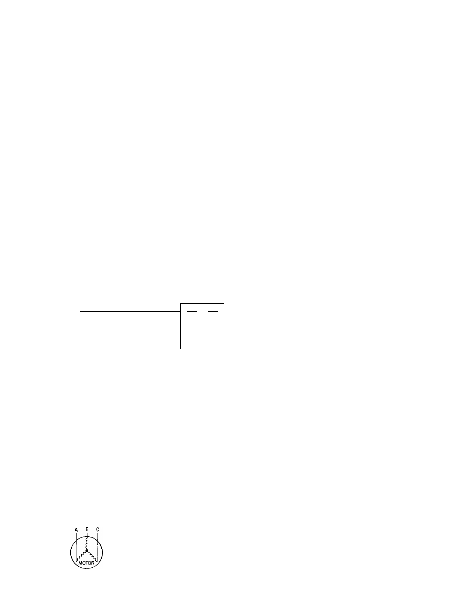
Fig. 10 — Field Power Wiring Connections
Operating voltage to eompressor must be within
voltage range indieated on unit nameplate. On 3-phase
units, voltages between phases must be balanced within
2% and the eurrent must be balanced within 10%.
Use the following formula to determine the % voltage
unbalanee.
% Voltage Unbalanee
average voltage
Example; Supply voltage is 460-3-60.
AB = 452 volts
BC = 464 volts
AC = 455 volts
Average Voltage
452 + 464 + 455
1371
457
Determine maximum deviation from average voltage;
(AB) 457 - 452 = 5 volts
(BC) 464 - 457 = 7 volts
(AC) 457 ~ 455 = 2 volts
Maximum deviation is 7 volts.
Determine % voltage unbalanee;
7
% Voltage Unbalance = 100
~
1-53%
This amount of phase unbalance is satisfaetory as it is
below the maximum allowable
2%.
IMPORTANT; If the supply voltage phase un
balance is more than 2%, contaet your loeal electric
utility company immediately.
Unit failure as a result of operation on improper line
voltage or excessive phase imbalance constitutes abuse
and may eause damage to eleetrieal eomponents. Sueh
operation would invalidate any applieable Carrier
warranty.
FIELD CONTROL WIRING — Install a Carrier-
approved accessory thermostat assembly aecording to
installation instruetions ineluded with aecessory. Loeate
thermostat assembly on a solid wall in the eonditioned
space to sense average temperature.
Route thermostat eable or equivalent single leads of
no. 18 AWG colored wire from subbase terminals
through eonduit in unit to low-voltage connections as
shown on unit label wiring diagram and in Fig. 11.
NOTE; For wire runs up to 50 ft, use no. 18 AWG insu
lated wire (35 C minimum). For 50 to 75 ft, use no. 16
AWG insulated wire (35 C minimum). For over 75 ft, use
no. 14 AWG insulated wire (35 C minimum).
Set heat anticipator settings as indicated in Table 3.
Settings may be changed slightly to provide a greater
degree of eomfort for a partieular installation.
Refer to accessory remote control panel instructions
as required.
THERMOSTAT ASSEMBLY
REMOVABLE JUMPER
I
h
PH
r
^ 1^ ^
^
[
r
] [
b
] 1 ^ Й Й ] Й [ ^ [ £ ] [
x
] [
h
] [ 1 ] [ K I
o
liJ
q
:
<
(r.
e >
z>
_j
CD
s
LOW-VOLTAGE TERMINAL BLOCK IN UNIT CONTROL BOX
Fig. 11 — Field Control Thermostat Wiring
Step 7 — Make Outdoor Air Inlet Adjustments
MANUAL OUTDOOR AIR DAMPER — All units
(except those equipped with a faetory-installed eeono-
mizer) have a manual outdoor air damper to provide
ventilation air. Damper ean be preset to admit up to 25%
outdoor air into return air compartment. To adjust,
loosen seeuring screws and move damper to desired
setting then retighten screws to seeure damper (Fig. 12).
OPTIONAL ECONOMIZER
Enthalpy Control Setting (loeation is shown in Fig. 13) —
For maximum benefit of outside air, set enthalpy control
to the A setting (Fig. 14).