Carrier 50DP016 User Manual
Page 6
Attention! The text in this document has been recognized automatically. To view the original document, you can use the "Original mode".
Step 3 — Field Fabricate Ductwork — Secure all
ducts to building structure. Use flexible duct connectors
between unit and ducts as required. Insulate and weather
proof all external ductwork, joints and roof openings
with flashing and mastic in accordance with applicable
codes.
Ducts passing through an unconditioned space must
be insulated and covered with a vapor barrier.
A minimum clearance is not required on 50DP,
DPE012,014 and 50DP016 units. The 50DP020 units
with electric heat require one-in. clearance the first 24 in.
of ductwork.
Outlet grilles must not lie directly below unit discharge.
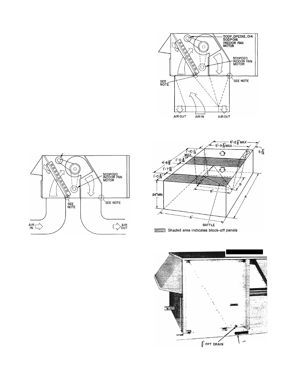
Step 4 — Make Unit Duct Connections — Unit
is shipped for through-the-bottom duct connections.
Ductwork openings are shown in Fig. 1 and 4. Duet
connections are shown in Fig. 5. Field-fabricated con
centric ductwork may be connected as shown in Fig. 6 and
7. Attach all ductwork to roof curb and roof curb base-
pans. Refer to installation instructions shipped with
accessory roof curb.
I
NOTE: Do not drill in this area, damage to basepan may resuit
In water ieak
Fig. 6 — Concentric Duct Air Distribution
50DR DPE0I2.0I4 50DP0I6
INDOOR FAN MOTOR
NOTE: Do not drill in this area, damage to basepan may result
in water leak.
Fig. 5 — Air Distribution — Through-the-Bottom
Step 5 — Trap Condensate Drain — See Fig. 4
and 8 for drain location. Plug is provided in drain hole
and must be removed when unit is operating. One 3/4-in.
half coupling is provided inside unit evaporator section
for condensate drain connection. An 8-1/2in. x 3/4-in.
diameter and 2-in. x 3/4-in. diameter pipe nipple coupled
to standard 3/4-in. diameter elbows provide a straight
path down through holes in unit base rails (see Fig. 9).
A trap at least 4 in. deep must be used and must be pro
tected against freeze-up.
NOTE: Dimension A, A1 and B, B1 are obtained from field-
supplied ceiling diffuser.
Fig. 7 — Concentric Duct Details
■
y--:
CONNECTION
Fig. 8 — Condensate Drain Details
11 DRAIN HOLES