Carrier 50DP016 User Manual
Page 12
Attention! The text in this document has been recognized automatically. To view the original document, you can use the "Original mode".
Variable Volume Units — Units suitable for use with
variable volume air handling systems are equipped with 2
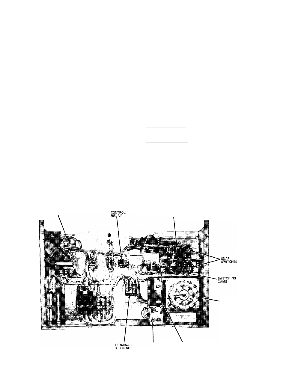
electric unloaders on the compressor. The control panel
for these units (Fig. 18) consists of a step controller, a
proportional thermostat, a 7-day timer and a power
switch.
Before starting unit, open compressor service valves
and liquid line shutoff valve. Be sure compressor crank-
ease heaters have been on for 24 hours and that crankcase
oil level indicates half full.
CONTROL SEQUENCE CHECKOUT
1. Turn on unit main power supply. Be sure unit is ready
to operate.
2. Set variable volume control panel POWER switch
at ON.
3. If supply air leaving unit is above 50 F (or other field-
set temperature), step controller will operate to de
energize compressor unloader solenoids (compressor
loads up) until set temperature is achieved. An interval
of 13.5 minutes is required to maximum loading
position. Refer to unit label diagram for unloader
sequencing. Also see Fig. 19.
4. Step controller, 7-day timer and proportional thermo
stat are factory set and adjusted. If other settings
or changes in adjustment are required, refer to dis
cussion of these items.
SEVEN-DAY TIMER ADJUSTMENT — Factory
settings are ON — 6:30 A.M.; OFF — 7:30 P.M. for each
of 7 days.
1. On the timer dial face (Fig. 18), loosen the thumb
screws which position the system ON and OFF
trippers.
2. Set trippers at desired system ON and OFF time
settings and tighten thumbscrews. Skipping a day(s) is
accomplished by removing trippers from the dial.
3. Set the timer by turning the dial face
clockwise
until
fixed pointer indicates correct day and time.
Do not
turn dial face counterclockwise. Do not move fixed
pointer.
PROPORTIONAL THERMOSTAT — The propor
tional thermostat. Fig. 18, monitors temperature of the
conditioned air leaving unit. On signal from the thermo
stat, sequence motor operates cam switches to load or
unload compressor to maintain thermostat setting.
Thermostat is factory set at 50 F ± 6 F but may be reset
between 0°F and 100F as follows:
Temperature Setting — Turn knob on front of case until
pointer indicates desired set point temperature. This is
the center point of proportional range.
Range Adjustment — Remove cover and turn adjustment
wheel until pointer indicates desired range.
If sequencer motor shaft constantly moves back and
forth, increase proportional thermostat range (about 5 F
at a time) until system is stable.
CYCLE-LOC
STEP
CONTROLLER
POWER
SWITCH
PROPORTIONAL
THERMOSTAT
SEVEN
DAY
TIMER
Fig. 18 — Control Panel, Variable Volume Limits
12