Carrier 50DP016 User Manual
Page 13
Attention! The text in this document has been recognized automatically. To view the original document, you can use the "Original mode".
STEP CONTROLLER — The step controller consists of
a reversible electric motor which drives a set of cams that
activate up to 5 snap-acting switches. Each cam is adjust
able to operate at any point on the 160 angular degrees of
camshaft rotation. The differential of each system may be
adjusted from a minimum of 5 angular degrees to a maxi
mum limited only by the 160 angular degrees of camshaft
rotation.
Rotational direction is controlled by the proportional
thermostat through the step controller feedback poten
tiometer and balancing relay.
Determining Switch Settings — Switches are factory set
at angular settings as shown m Fig. 19 (also shown on unit
label diagram). To reset, if desired, determine angular
differential for each switch and between switches. Then
determine minimum differential or throttling range of
proportional thermostat to provide desired step con
troller differential or throttling range. This range should
be wide enough to prevent rapid cycling from one
capacity step to another. Then adjust cams to new settings
as required.
MAKE
POINT
BREAK
POINT
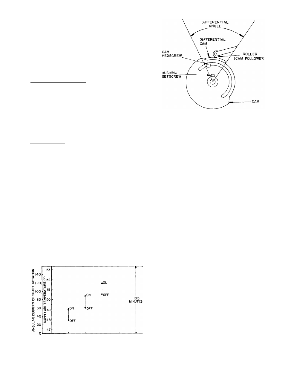
Fig. 20 — Step Controller Cam Adjusting
Details (Motor End View)
#
#
Cam Adjustments — The step controller is shipped with
cams set to operate switches (i.e. compressor unloaders)
as shown in Fig. 19. All switches are closed (compressor
unloaded). The shaft is positioned all the way counter
clockwise (as viewed from motor end).
Using the following procedure, first adjust all operating
points in one direction of motor drive. Then reverse
motor direction and adjust switch differentials. Use
potentiometer wiper as an approximate indicator of
angular adjustments using angular displacement scale
mounted on potentiometer back plate. Also see Fig. 20.
160
I
2
3
4
STEP CONTROL SWITCH
Fig. 19 — Step Controller Sequence
1. Loosen all bushing setscrews with a 1/16-in. Allen
wrench. Loosen all cam hex screws with a 3/16-in.
open-end wrench.
If setscrews are not accessible from top of controller,
operate motor to rotate cams and bushings by shorting
terminals R and B for counterclockwise rotation and
terminals R and W for clockwise rotation.
2. Momentarily de-energize motor to permit motor to
recycle to start position. Jumper terminals R and W to
run motor camshaft to desired position for operating
first switch. Stop motor in this position by removing
jumper between terminals S and T.
3. Starting with first switch, turn cam clockwise until
switch makes an audible “click” as roller moves up cam
rise to higher level. This is the operating point. Lock
bushing setscrews.
operating point of each of remaining switches in
manner. Advance motor by momentarily jumper-
Set
like manner.________
ing terminals S and T.
5. Set switch differential by reversing motor (short
terminals R and B) and running it to desired break
point. Stop motor at this point by de-energizing power
at LI (POWER switch off). Start at last switch and
progress to first switch.
Move differential cam clockwise so that roller is on
high part of cam. Be sure that switch is at make
position. To check this, manually lift roller assembly
to make switch. Move differential cam counterclock
wise until roller drops to low level of cam. At this
point, switch should break. Lock the hex screw.
6. Check settings by performing Control Sequence
Checkout.
7. If 115-volt to step controller is de-energized, timer
recycles to start point when power is restored.
13