Carrier 50BK User Manual
Page 6
Attention! The text in this document has been recognized automatically. To view the original document, you can use the "Original mode".
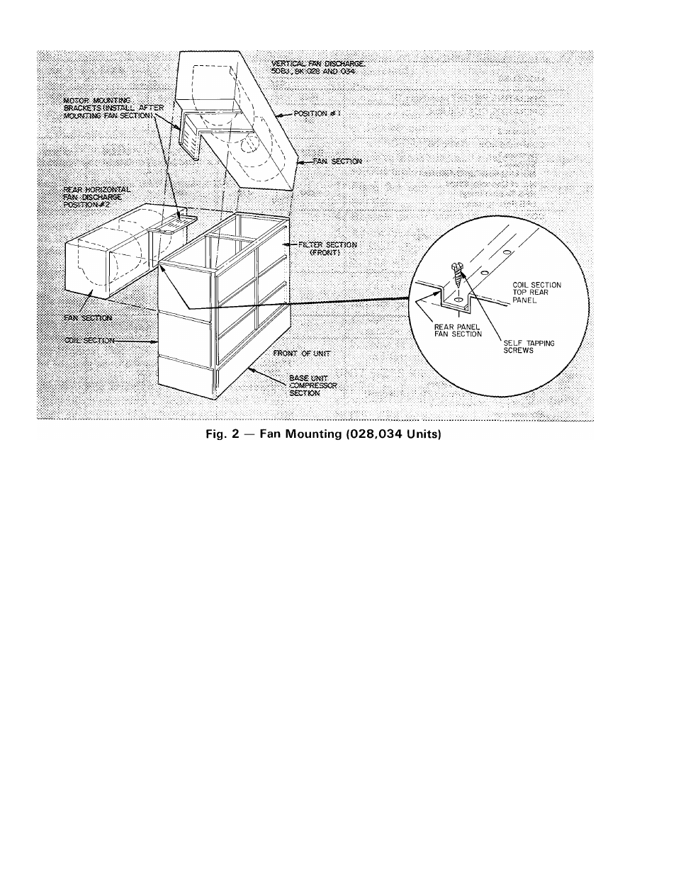
To set up sizes 50BJ,BK028 and 034 units for
vertical discharge (Fig. 2):
1. Remove:
a. Front, rear and end panels of fan section.
b. Upper-rear and end panels of coil section.
c. Filters from coil section.
d. Fasteners holding filter frame top. Push out
frame away from coil section frame.
2.
Lift up and position fan section on coil section
(Fig. 2).
3.
Fasten fan-section frame to coil-section frame
with
fasteners
provided;
then
reposition
and
refasten the filter frame moved in step Id.
4. Install the following per Installation Step 6:
a. Motor mounting frame angles.
b. Motor on motor-plate assembly.
c. Motor-plate assembly on frame angles.
d. Balance of drive package components.
5. Adjust the following per Installation Step 8:
a. Fan wheel alignment.
b. Shaft alignment.
c. Pulleys.
d. Fan belts.
6. Replace panels as follows:
a. Rear coil-section panels, front and rear fan-
section panels.
b. All end panels.
Unit sizes 50BJ,BK044,054 and 064 are shipped
with vertical discharge as standard. Other fan posi
tions are available as a factory-installed option.
Step 6 — Install Fan Motor. Unit 50BJ,BK028
and 034 only. (All other units have factory-installed
motors.) Install items after fan section frame has
been placed in position on coil section.
NOTE:
Place
plywood
over
evaporator
coil
to
prevent damage while installing motor and mounts.
To install motor:
1.
Fasten motor mounting angle bracket to fan
section. Use Fig. 2 or 3 for position reference
and Fig. 4 for assembly guidance. Be sure that
lips of angle brackets are around fan section
frame and that slots for motor mounting plate
face each other.
2.
Position motor on motor plate (Fig. 5) and
fasten with fasteners provided.
3.
Lift motor-plate assembly and slide into motor
mounting angles as shown in Fig. 4. Plate fits in
angle
slots.
On
vertical
mounts,
the
motor
mounting assembly can be lowered to bottom of
motor support channels.
4.
Assemble and install motor adjusting screws as
shown in Fig. 6. Drive roll pins into screws to
prevent the screws from backing out during
motor position adjustment.
t