Step 13 — install unit drain line, Fig. 18 — condensate drain – Carrier 50BK User Manual
Page 12
Attention! The text in this document has been recognized automatically. To view the original document, you can use the "Original mode".
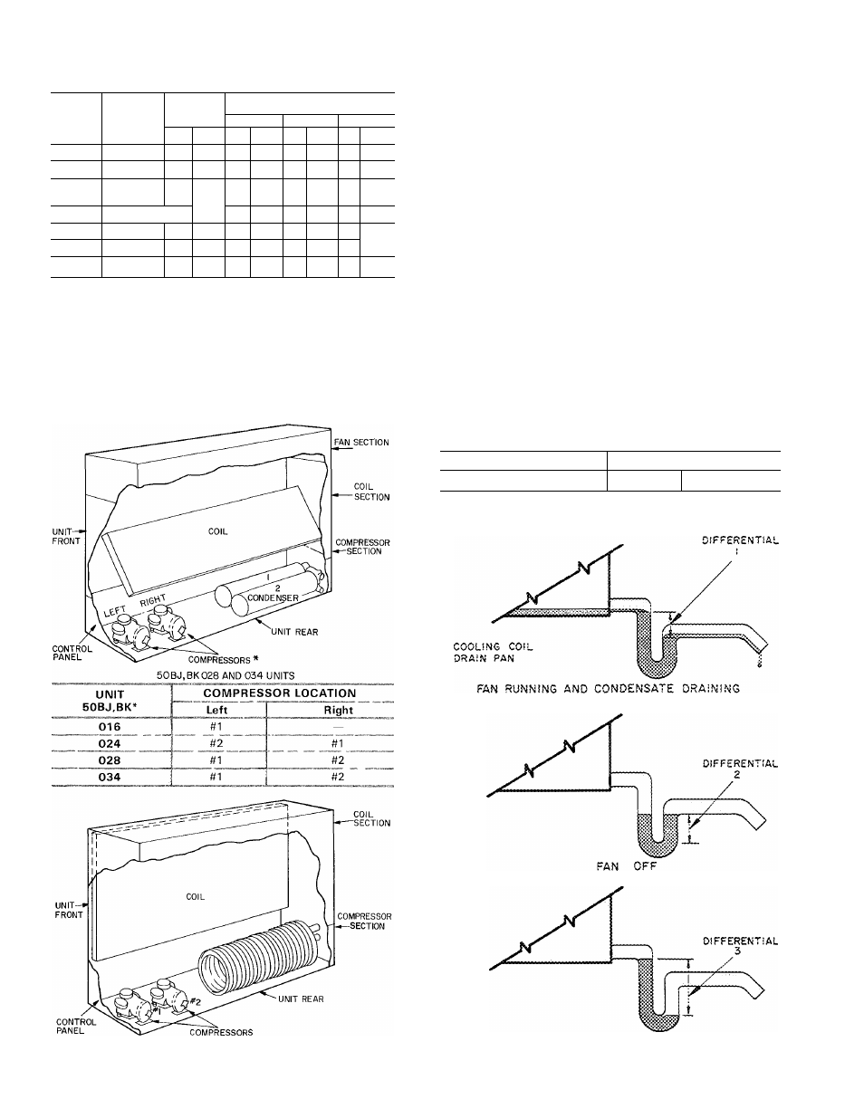
Table 4 — Recommended Line Sizes (in.)
(50BK Condenserless Models)
HG — Hot Gas Line (OD in ]
L — Liquid Line (OD in )
‘Sweat connections
UNIT
50BK
CONN.
LENGTH OF LINE (ft)
SYSTEM
SIZES*
20
40
60-80
L
HG
L
HG
L
HG
L
HG
016
—
%
^Ve
Ve
1'/s
ys
P/s .
ys
P/s
024
1 & 2
%
Vs
Y
b
ys
Ye
P/s
ys
P/s
028
1
%
^Vв
Va
1'/s
V
b
p/s
ys'
p/s
2
Ys
ys
Y
b
ys
Ya
p/s
Ps
p/s
034
1 & 2 1 %
r/s
Y
b
1
V
b
Va
p/s
ys
p/s
044
1 & 2
%
IVs
V
b
V/a
V
b
p/s
ys
p/s
054
1 & 2
%
lys
V
b
P/s
V
b
p/s
ys
p/s
064
1 & 2
ys
^Уe
V
b
P/s
Va
p/s
ys
p/s
Step 13 — Install Unit Drain Line
Install a trapped condensate drain line at unit
drain
connection
(Fig.
12).
The
drain
requires
standard pipe connected to condensate pan nipple
as shown in Table 5. Figure 18 shows proper
trap design.
Determine design negative static pressure. This
pressure is not the same as fan total pressure,
which includes pressure losses downstream as well
as upstream from the indoor air fan. Always assume
the worst conditions, such as having return air
filters clogged with dirt.
Referring to Fig. 18, Differential 1 must be equal
to or larger than negative static pressure at design
operating conditions. Store enough water in trap to
prevent losing seal (Differential 2). This differential
must be equal to or larger than one-half the maxi
mum negative static pressure. When the fan starts.
Differential 3 is equal to the maximum negative
static pressure.
Table 5 — Condensate Drain Connections (in.)
UNIT SIZE :
016,024
028,034
044,054,064
PIPE SIZE ;
1
P/4
P/2
50BJ.BK044-064
UNITS
Fig. 17 — Refrigerant Systems (016-064)
TRAP CONDITION WHEN FAN STARTS
Fig. 18 — Condensate Drain
II