Step 14 — make electrical connections, Important: ff supply vorage phase «a- balaace – Carrier 50BK User Manual
Page 13
Attention! The text in this document has been recognized automatically. To view the original document, you can use the "Original mode".
Do not use drain line smaller than size listed in
Table 5. If required, cut hole in panel for drain line.
Piteh drain downward toward an open drain sump.
Provide a trap at least 3 in. high with plugged tee for
cleaning. Fill trap with water to make an air seal.
Observe all sanitary codes.
Step 14 — Make Electrical Connections
GENERAL — Provide an adequate fused dis
connect switch per NEC within sight from the unit.
Provision for locking switch open (OFF) is ad
visable to prevent power from being turned on when
unit is being serviced.
On all units, power may be supplied thru a branch
circuit. Branch circuit protection is provided in these
units by manual reset circuit breakers. Branch
circuit must be in accordance with NEC or local
code, whichever takes precedence. Power supplied
to auxiliary equipment, such as fan motors for air
cooled condenser or for cooling tower, must be
run separately.
^POWER WIRING — Conduit opening for 016-034
units is on back of unit near control box. Conduit
opening for 044-064 units is on top of unit near
control box. On all sizes, field power connections
are made at a terminal block within the control box
(see Fig. 19). Refer to Table 6 for maximum wire
size at terminal block.
50BJ,BKOI6-034
FIELD
POWER
SUPPLY
---------------------------------------0L3 0-
------ O L2 O-
----------- OLI O-
-01
EQUIP. GND.
BLU
YEL
BLK
50BJ.BK 044-064
TBI
FIELD
POWER
SUPPLY
L3
L2
LI
llU
—
ÜU
rm
ÜU
IfTl—1
---------------- —7
iV 1 1
EQUIP. GND,
-------------------FIELD WIRING
-------------------- FACTORY WIRING
Fig. 19 — Field Power Wiring Connections
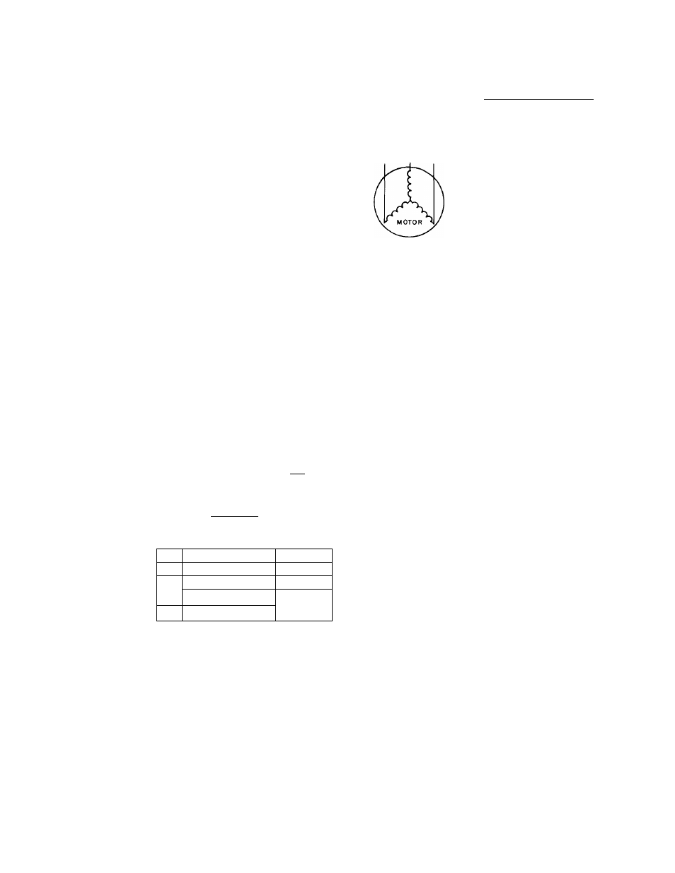
Supply voltage must be in accordance with name
plate voltage. On 3-phase units, voltage between
phases must be balanced within 2% and current
within 10% with compressor running. If supply
voltage is not in accordance with nameplate voltage,
a phase unbalance may occur. Voltage at com
pressor must be within the minimum and maximum
shown in Table 7.
Contact local power company for line voltage
corrections. Never operate a motor where a phase
unbalance in supply voltage is greater than
2%.
Use
the following formula to determine the % voltage
unbalance:
max voltage deviation
% Voltage _ jQQ from average voltage
Unbalance ~
average voltage
Example; Supply voltage is 240-3-60.
A B r, AB = 243 volts
BC = 236 volts
AC = 238 volts
Average Voltage =
Average Voltage
243 + 236 + 238
717
= 239 volts
Determine
maximum
deviation
from
average
voltage:
(AB) 243 — 239 = 4 volts
(BC) 239 — 236 = 3 volts
(AC) 239 -- 238 = 1 volt
Maximum deviation is then 4 volts. To determine
the % voltage unbalance:
4
1
Voltage Unbalance = 100 x
239
= 1.7%
This amount of phase unbalance is satisfactory
since it is below the maximum allowable of 2%.
IMPORTANT: ff supply voRage phase «a-
balaace
h
more than 2%, contaci your local
electric tiiility company immedjaieiy.
^
Compressor operation on improper line voltage
or excessive phase unbalance may be considered
abuse and anv resulting damage may not be covered
by Carrier warranty.
All wiring must be in accordance with local or
NEC regulations.
EIELD CONTROL WIRING — On extended volt
age (208-230-v) units, control transformer is factory
wired for 208-v usage. If unit is to be used on 230-v
system, reconnect primary wiring on transformer as
shown on unit wiring diagram.
When accessory timer control panel is used,
connect
panel
to
factory-supplied
control
panel
as indicated on unit label diagram.
^WINTER
START-UP
PACKAGE
—
On
50BK
044-064 units, an accessory winter start-up package
is available for providing a 3-minute time delay by
shorting out the low-pressure switch on each com
pressor. This enables each compressor to start even
during low ambient conditions.
^HEATING COILS — Accessory heating coils are
available for field installation. Separate installation
instructions are shipped with the accessory (016-034
only). For 50BJ,BK044-064 units, refer to latest
39E (size 32) literature.
12