Control sequence – Carrier 50BK User Manual
Page 19
Attention! The text in this document has been recognized automatically. To view the original document, you can use the "Original mode".
CONTROL SEQUENCE
All 50BJ,BK Units — The indoor fan circuit
breaker (IFCB) must be closed for the control
circuit to be energized. When breaker is closed, the
SYSTEM light will be on.
The 044-064 units are equipped with a switch
labeled STANDBY. When switch is closed, the
indoor fan contactor (IFC) is energized and the
indoor fan will start and run continuously. A light
labeled FAN will come on. To use accessory timer
control, switch must be put in STANDBY position.
All units are equipped with the improved Honey
well W7100 discharge air controller. Controller has
3 control knobs: set point, reset and control band.
Controller regulates the leaving air temperature to
the set point. A setting below 50 F may decrease
unit efficiency due to use of hot gas bypass at light
loads. The reset knob adjusts reset control range
from 5 F to 20 F. The reset feature requires field-
supplied components and wiring. The control band
knob adjusts controller for the required number of
stages. The control band should be set at 6 F for the
016-034, 054 and 064 units, and 8 F for the 044 units.
Increasing control band setting above these recom
mended settings will decrease compressor cycling
and
increase
leaving
air
temperature
variations.
Decreasing setting will
not
reduce discharge air
temperature variations but will increase compressor
cycling.
The controller is also factory equipped with 2
fixed resistors. One resistor corrects for the number
of steps. This is done by placing a 1/4-watt, 5%-
m
8
on micro-
resistor
across
terminals
m
and
processor. A 3-stage, 300-ohm resistor is used on the
016 unit. A 4-stage, 400-ohm resistor is used on 044
units and a 600-ohm resistor is used on 024-034,
054 and 064 units. A second 510-ohm resistor is
connected between terminals 0 and [V] to indi
cate unit does nt have an economizer. These units do
not have a factory-supplied eeonomizer. If a field-
supplied economizer is added, remove the 510-ohm
resistor.
Consult
Carrier
Corporation
for
more
details.
If the discharge air deviates 1°F above or below
the control band while unit is running, a cooling
capacity stage will either be added or removed
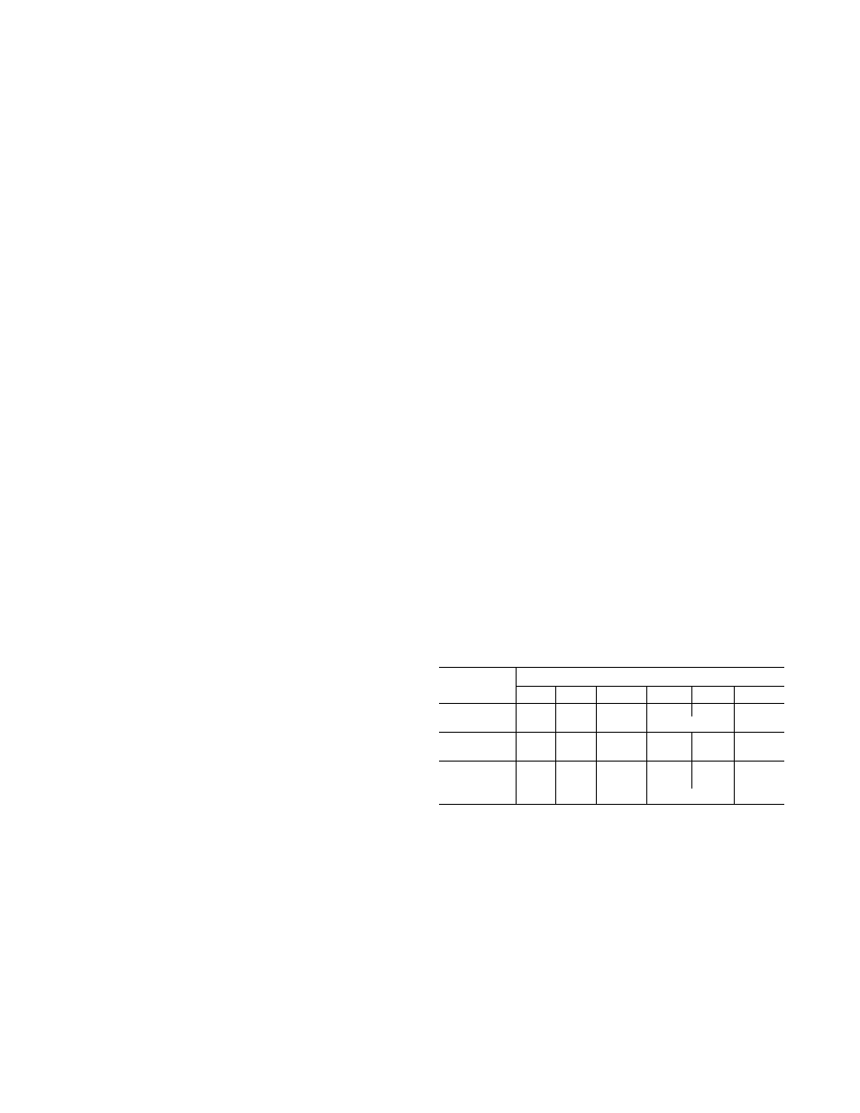
according to the loading sequence table found on
page 18. Additional capacity steps will be turned on
or off until discharge air temperature is within
control band or is charging at a rate that will allow
it to be within control band within 10 minutes. The
controller also has a fixed guaranteed minimum
on and off time of 4 minutes to prevent compressor
cycling.
These units are equipped with a Time Guard®
circuit. This circuit prevents compressor no. 1 from
restarting until 4 minutes, 45 seconds have elapsed
from last shutdown. Compressor no. 2 will not
restart until 6 minutes, 10 seconds have elapsed.
Each compressor is equipped with a high-pressure
switch (HPS), discharge gas thermostat (DGT) or
internal
protection
(IP)
and
low-pressure
switch
(EPS). If any of these “trip”, the compressor will
shut down. If, after 4 minutes, 45 seconds for com
pressor no. 1 and 6 minutes, 10 seconds for compres
sor no. 2, the switch resets, compressor no. 1 will
restart within 15 seconds and compressor no. 2
within 19 seconds.
The 50BK condenserless units are equipped with
a liquid line solenoid (ELS). When a stage calls for
compressor shutdown, the liquid line solenoid will
close first. The compressor will continue to run until
the low-pressure switch opens.
Loading Sequence
MODEL
STAGE
50BJ.BK
1
2
3
4
5
6
016
33%
67%
100%
—
—
—
024
17%
34%
50%
67%
84%
100%
028
17%
34%
50%
67%
84%
100%
034
17%
34%
50%
67%
84%
100%
044
25%
50%
75%
100%
------
—
054
19%
38%
57%
63%
84%
100%
064
17%
34%
50%
67%
84%
100%
18