Data – Carrier 48SS User Manual
Page 19
Attention! The text in this document has been recognized automatically. To view the original document, you can use the "Original mode".
lv‘-| ij.fi;;
data
Condensate trap
— A 2-in condensate trap must be field
supplied.
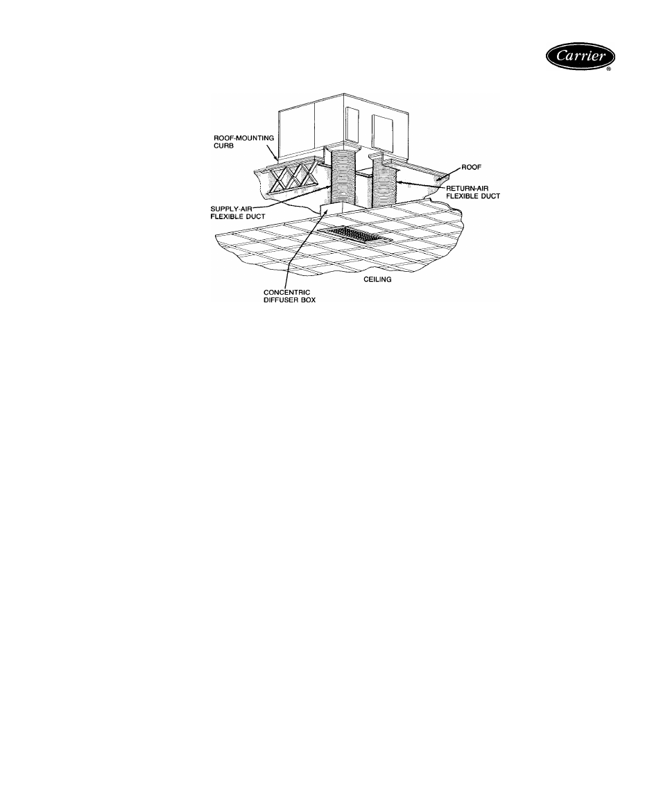
Ductwork
— Secure downflow discharge ductwork to roof
curb For horizontal discharge applications, attach ductwork
to unit with flanges
To convert a unit to downflow discharge or horizon
tal discharge
— Units are equipped with factory-installed
duct covers on both the downflow and horizontal openings
Remove appropriate duct panel covers for intended dis
charge application Units with downflow option do not re
quire duct panel cover removal
Thermostat
— To achieve simultaneous economizer cool
ing and mechanical cooling, use of 2-stage cooling thermo
stat is recommended for all units equipped with an accessory
economizer
Airflow
— Units are draw-thru on cooling and blow-thru
on heating
Maximum cooling airflow
— To minimize the possibility
of condensate blow-off from evaporator, airflow through units
should not exceed 450 cfm/ton
Minimum cooling airflow
is 350 cfm/ton
Minimum ambient operating temperature
for all stand
ard units is 40 F. With accessory low ambient temperature
kit, units can operate at temperatures down to 0° F
19