Exhaust door removal (see fig. 21), Evaporator and condenser coils removal – Carrier 1995 Room Air User Manual
Page 8
Attention! The text in this document has been recognized automatically. To view the original document, you can use the "Original mode".
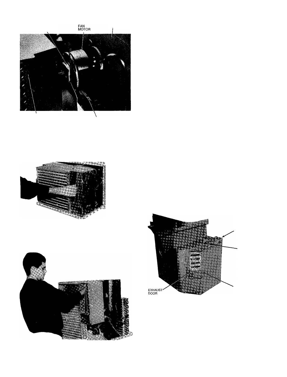
FAN MOTOR
CLIP (SPRING)
PARTITION
AIR HANDLING SYSTEM
REMOVAL SCREW
LEFT SIDE SCREW TOP
REAR SIDE
PARTITION SCREW
Fig. 18 — Removing Fan Motor Ciip
Fig. 19 — Disengaging Vertical Air Deflector
Evaporator and Condenser Coils Removal (See
Fig. 16)
1
Recover all refrigerant from system using a Carriei
Totalclaim® or Carrier Totalsave® recovery system,
or a comparable refrigerant recovery system Refer to
Service section, page 1
2 Remove chassis from casing See Chassis Removal in
structions, page 4
3 Remove air-handling system See Air-Handling System
Removal instructions, page 7
4 Cut interconnecting tubing and remove evaporator coil
from basepan by removing 2 evaporator screws See
Fig 16
5 Cut interconnecting tubing and remove condenser coil
from basepan by removing 2 condenser coil screws See
Fig 16
6 Reverse above procedure for reassembly Reconnect tub
ing using field-supplied slip coupling Recharge system
Exhaust Door Removal (See Fig. 21)
1 Remove chassis from casing See Chassis Removal in
structions on page 4
2
Remove control box from chassis See Control Box
Removal instructions, page 5
3 Remove air-handling system See Ait-Handling System
Removal instructions, page 7
4 Remove 3 screws securing partition to indoor plastic scroll
(See Fig 22 and 24 )
5 Carefully separate sheet metal partition slots from scroll
tabs on both sides by spreading sheet metal sides apart
Remove scroll from sheet metal partition (See Fig 6 )
Exhaust door and cable assembly from door to rotary
lever (Fig 21) are now exposed for required repairs or
adjustments
6 Reverse above procedure for reassembly
ROTARY LEVER
CABLE
EXHAUST DOOR
SPRING CUP
Fig. 21 — indoor Plastic Scroll Assembly
-.'.if
Fig. 20 — Removing Air-Handling System