A caution, Fig. 15 — electronic control board, Capacitor removal – Carrier 1995 Room Air User Manual
Page 7: Air sweep motor removal, Air-handling system removal
Attention! The text in this document has been recognized automatically. To view the original document, you can use the "Original mode".
,
,,—
lcd
/y.
■ S“™
f
------- RELAY
BOARD
FLYING
WIRE
(SHOWN
CONNECTED
TO 220 V )
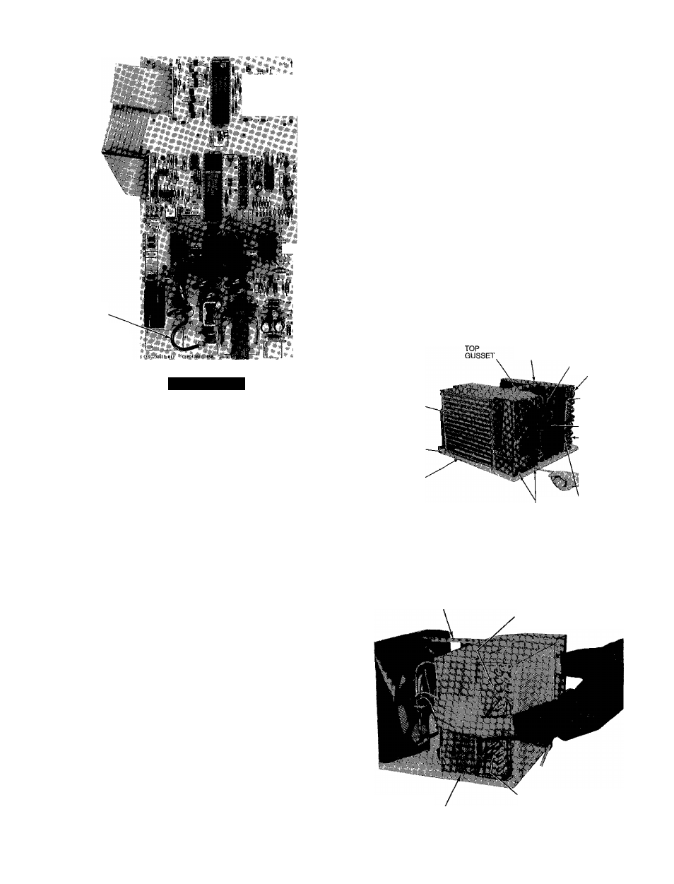
A CAUTION
When replacing electronic control board, be sure
flying wire is attached to the 220-V connection or
electronic control board will be damaged
Fig. 15 — Electronic Control Board
Capacitor Removal
Slide chassis out of casing far enough to access capac
itor located on back side of partition
Pull back rubber boot
Before disconnecting, discharge capacitor by shorting ca
pacitor across terminals
Remove screw fastening capacitor strap to partition and
remove strap (See Fig 6 )
Carefully disconnect wires from capacitor terminals
Reverse above procedure for reassembly
Air Sweep Motor Removal
1 Remove control box and electronic control board See
Control Box Removal instructions, page 5, and Elec
tronic Control Board Removal instructions, page 6
2 Carefully disconnect air sweep motor (Fig 14) wire ter
minations from electronic control board
3 Carefully pull plastic air sweep motor cam from shaft
See Fig 11
4 Remove 2 screws securing air sweep motor to control
box and remove motor
5 Reverse above procedure for reassembly
Air-Handling System Removal
1 Remove chassis from casing See Chassis Removal in
structions, page 4
2 Remove control box See Control Box Removal in
structions, page 5
1
8
9
10
Remove 2 screws securing partition to basepan as shown
in Fig 16, and 2 screws on left side (Fig 17), and one
screw on rear side of partition (Fig 18), in area of
motor
Remove 2 screws securing evaporator scroll to evapo
rator tube sheet See Fig 17
Remove 4 screws (2 on right side and 2 on left side)
securing condenser orifice to condenser coil tube sheet
See Fig 16 for location of right-side screws, left-side
(2) screws are in similar location on left side
Remove compiessor terminal cover Disconnect wires
from compressor and external oveiload protector ter
minals Label wires to aid in reassembly See Fig 16
Remove fan motor clip See Fig 18
Carefully disengage one of the vertical air deflectors,
allowing access to assist in removing air handling sys
tem assembly See Fig 19
Carefully lift assembly from chassis See Fig 20
Reverse above procedure for reassembly, ensuring air
handling system is positioned correctly Tighten all screws
CONDENSER
ORIFICE
EVAPORATOR
COIL
EVAPORATOR
SCREW
(1 OF 2}
BASEPAN
COMPRESSOR
TERMINAL
/COVER
CONDENSER
COIL
CONDENSER
ORIFICE
SCREW (1 OF 4)
■COMPRESSOR
—CONDENSER
COIL SCREW
{1 OF 2)
[SEE NOTE 1)
CONDENSER
PARTITION ORIFICE SCREW
SCREWS (2)
(10F4)
NOTES
1 Second condenser coil screw is located on the back of unit
2 Third and fourth condenser orifice screws are located in same
area on opposite end of condenser orifice
Fig. 16 — Unit Chassis
TOP GUSSET
SCREW SECURING
EVAP SCROLL TO
EVAP TUBE SHEET
LEFT SIDE
PARTITION SCREW
SCREW SECURING
EVAPSCROLL TO
EVAP TUBE SHEET
Fig. 17 — Preparing to Lift Air-Handling System