Carrier 1995 Room Air User Manual
Page 2
Attention! The text in this document has been recognized automatically. To view the original document, you can use the "Original mode".
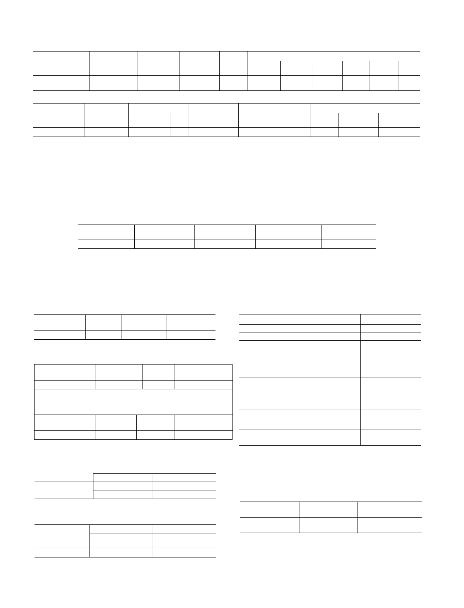
Table 1 — Physical and Electrical Data (Single-Phase, 60 Hz)
SERVICE/
DISCRETE NO
CASING
(See Table 5)
COOLING
CAPACITY
(Btuh)‘
R-22
CHG
(OZ.
± 05)
WET
BULB
At F
NAMEPLATE
Volts
Voltage
Range
Amps
Watts
EER
(DOE)
PF
(%)
73XCB118301E
305
18,000/
17,000
37 0
135
230/208
253-187
8 3/8 8
1870/
1840
96
99
SERVICE
DISCRETE NO.
CAPACITOR
(See Table 4)
FAN MOTOR
COMPRESSOR
(See Table 2)
COMPRESSOR-START
THERMISTOR
(See Table 3)
CAPILLARY (See Tables 6 and 7)
Carrier
Part Number
FLA
Data
Insertion
Number
of Tubes
73XCB118301E
RC-2
25901051
1 24
D-5
Z-1
CD-3
CI-1
3
LEGEND
AHAM — Association of Home Appliance Manufacturers
ANSI — American National Standards Institute
DOE
— Department of Energy
EER
— Energy Efficiency Ratio
FLA
— Full Load Amps
PF
— Power Factor
At — Entering wet-bulb temperature minus leaving wet-buib temper
ature based on 67 F room wet-bulb temperature and 95 F dry-
bulb outside-air temperature If conditions vary, wet-bulb At will
vary
*Based on AHAM Standard RAC-1 and ANSI Z234 1
Table 2 — Compressor
KEY NUMBER
(See Table 1)
REPLACEMENT
PART NUMBER
OIL RECHARGE
(OZ)
VOLTS
(Slngle-Ph, 60 Hz)
LRA
FLA
D-5
P033-1822
80
230/208
44 0
128
LEGEND
FLA — Full Load Amps
LRA — Locked Rotor Amps
Table 3 -- Compressor-Start Thermistor
Table 8 — Receptacle, Fuse Type, Wire Size
KEY NUMBER
CARRIER
VENDOR
RESISTANCE
(See Table 1)
NUMBER
NUMBER
(Ohms)
Z-1
42320001
CM305C20C
25
Table 4 — Capacitor
KEY NUMBER
(See Table 1)
CARRIER
NUMBER
MFD
VOLTS
RC-2
05706030
30/5
370
Table 5 - Casing Dimensions (in.)
KEY NUMBER
(See Table 1)
HEIGHT
WIDTH
DEPTH
»
305
163/4
253
/
1
6
233/4
Table 6 — Capillary Data
KEY NUMBER
DIMENSIONS (in}
(See Table 1)
Length (± 002)
I D ( ± 002)
CD-3
1 Tube — 47 0
1 Tube - 054
2 Tubes — 29 3
2 Tubes — 054
Table 7
—
Capillary Insertion
KEY NUMBER
(See Table 1)
DEPTH (In.)
DEPTH (in )
Condenser Coil
Connection Tube
Evaporator Coil
Connection Tube
CM
1
1
UNIT NAMEPLATE VOLTAGE
230/208
MAXIMUM NAMEPLATE AMPS
12
OUTLET RATED VOLTS/AMPS
250/15
RECEPTACLE CONFIGURATION
MFR PART NO
Hubbell
5661
P &S
5661
GE
GE4069-1
Arrow-Hart
5661
TIME-DELAY FUSE OR CIRCUIT
BREAKER SIZE (AMPS)
15
FUSE TYPE
Cartridge
RECOMMENDED AWG
WIRE SIZE*
14
LEGEND
AWG — American Wire Gage
‘Based on copper wire at 60 C temperature rating
Table 9 - Electronic Control
ITEM
CARRIER PART
INDOOR
NO
THERMISTOR
COOLING-ONLY
CONTROL
CEPL130015-01
912-710011-P2216
□El